Research on the calibration method of structural parameters of five-axis magnetorheological machine tool with double swing table
-
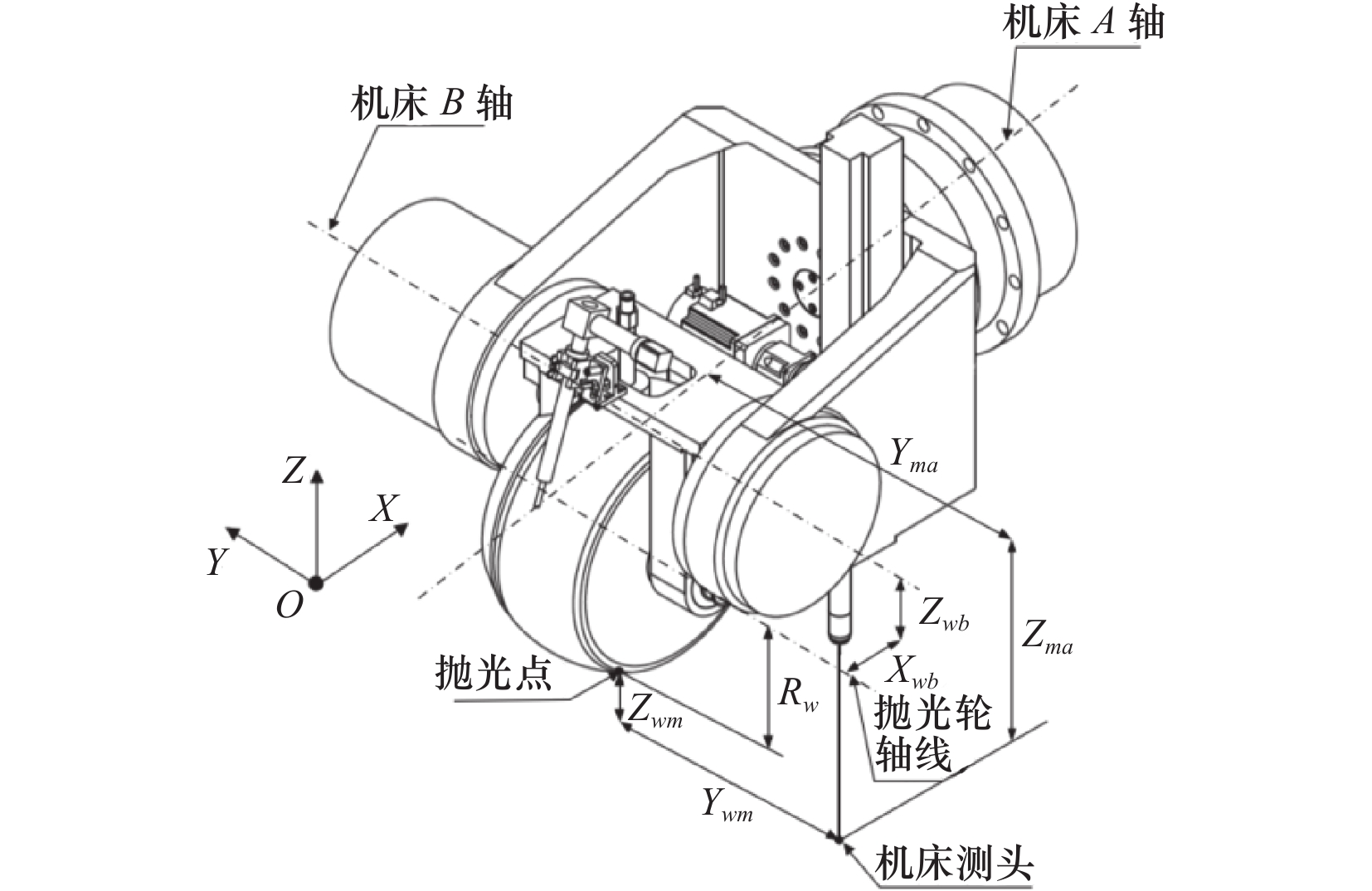
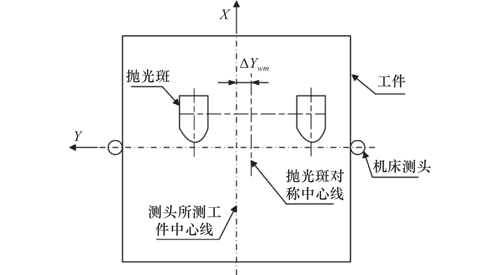
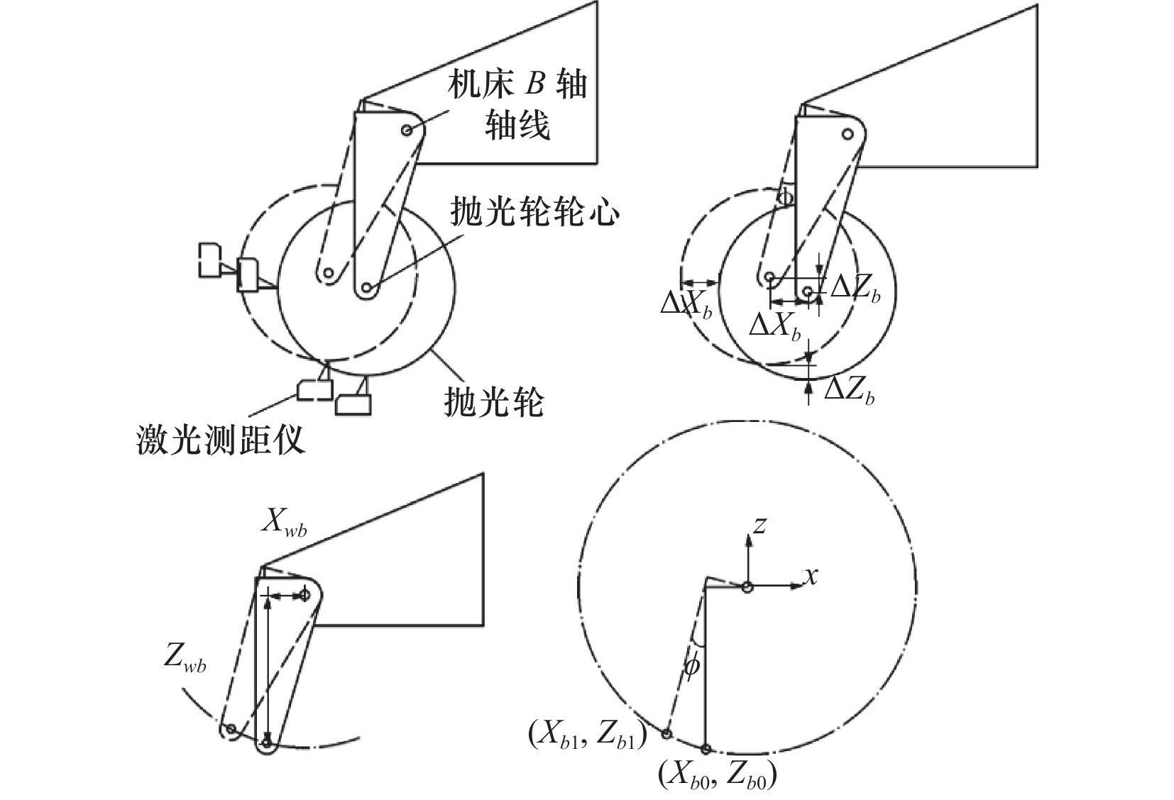
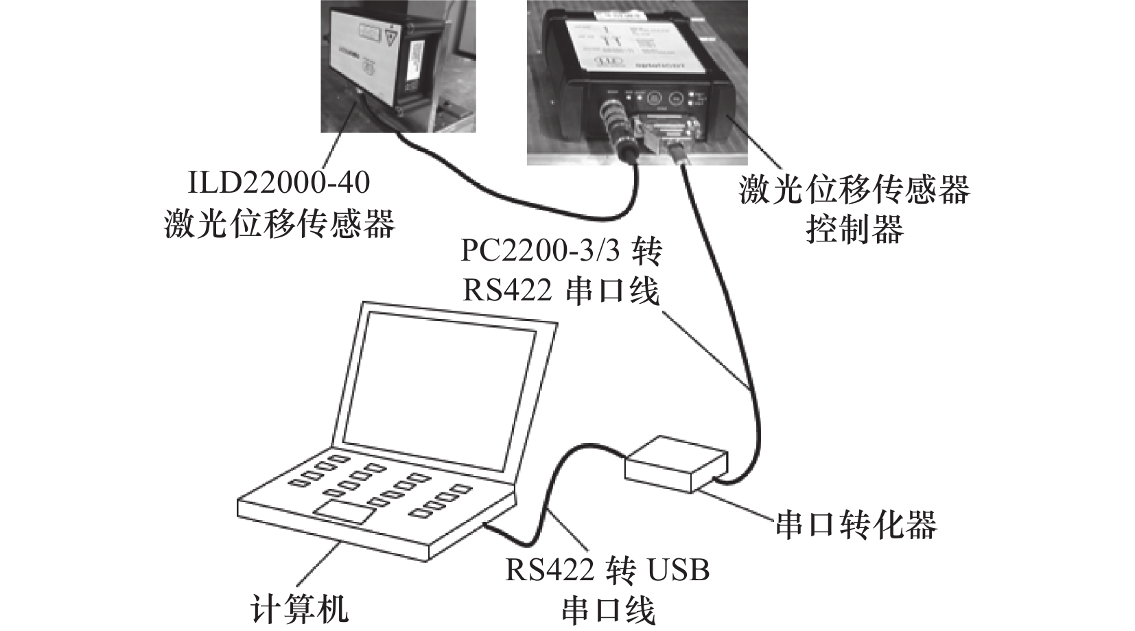
摘要: 为实现AB双摆台磁流变机床五轴联动结构参数的快速精确标定,建立了1种高效准确的测量方法。通过分析机床结构特点及现有方法存在的问题,对目标标定参数进行分解,利用激光位移传感器与在机测头分别建立了A轴与测头、测头与抛光点、B轴与抛光点标定方法及模型。在此基础上,开展标定及验证实验,在验证试验中,实际值与预测值在X、Y、Z方向误差均小于6 μm。实验结果表明该结构参数标定方法简单可靠,满足磁流变机床的使用需求。Abstract: In order to realize the fast and accurate calibration of five-axis linkage structure parameters of AB double swing magnetorheological machine. An efficient and accurate measurement method was established. By analyzing the structural characteristics of the machine tool and the problems existing in the existing methods, the target calibration parameters are decomposed. The calibration methods and models of A-axis and probe, probe and polishing point, B-axis and polishing point are established respectively by using laser displacement sensor and on-board probe. On this basis, calibration and verification experiments were carried out. In the verification experiments, the errors of actual and predicted values in X, Y and Z directions were all less than 6 μm. The experimental results show that the proposed calibration method is used to verify the simpleness and reliability, which can meet the requirements of magnetorheological machine tools.
-
Key words:
- MRF /
- five-axis machine tool /
- structural parameters /
- calibration /
- laser displacement sensor
-
表 1 不同A轴角度下测头坐标值以及对应偏移量
A/(°) Y/mm ΔY/mm Z/mm ΔZ/mm 0 左:−502.698 0 −193.599 0 10 −404.282 98.416 −227.58 −33.981 15 −357.667 145.031 −250.869 −57.270 20 −313.257 189.441 −278.132 −84.533 0 右:−704.354 0 −193.599 0 −10 −807.178 −102.824 −177.229 16.370 −15 −859.267 −154.913 −175.825 17.774 −20 −911.283 −206.929 −178.959 14.640  下载: 导出CSV
表 2 不同A轴角度下结构参数计算值
序号 A/(°) Yma/mm Zma/mm 1 10 −144.994 −579.440 2 15 −144.989 −579.445 3 20 −144.985 −579.453 4 −10 −144.967 −579.456 5 −15 −144.960 −579.453 6 −20 −144.978 −579.456
下载: 导出CSV
表 3 不同B轴角度下抛光轮最低点坐标值以及对应偏移量
序号 B/(°) X/mm ΔX/mm Z/mm ΔZ/mm 1 0 −290.967 0 −85.296 0 2 10 −264.862 −26.105 −87.690 2.394 3 15 −252.070 −38.897 −90.584 5.288 4 20 −239.573 −51.394 −94.582 9.286 5 −10 −317.092 26.125 −87.468 2.172 6 −15 −329.914 38.947 −90.253 4.957 7 −20 −342.442 51.475 −94.146 8.850
下载: 导出CSV
表 4 不同B轴角度下结构参数计算值
序号 B/(°) Xwb/mm Zwb/mm 1 10 −0.629 −150.387 2 15 −0.632 −150.376 3 20 −0.635 −150.377 4 −10 −0.649 −150.391 5 −15 −0.647 −150.393 6 −20 −0.642 −150.390 平均相对位置关系(Xwb, Zwb) −0.639 −150.385
下载: 导出CSV
表 5 不同A轴角度下测头Y向坐标预测与实际值
A/(°) 预测位置Y/mm 实际位置Y'/mm ΔY/mm 16 −348.601 9~
−348.590 5−348.591 0 −9 −796.796 1~
−796.773 7−796.790 0 −22 −931.987 8~
−931.965 4−931.982 0
下载: 导出CSV
表 6 不同A轴角度下测头Z向坐标预测与实际值
A/(°) 预测位置Z/mm 实际位置Z'/mm ΔZ/mm 16 −256.017 2~
−255.997 8−256.004 0 −9 −178.054 3~
−178.052 3−178.059 −0.004 7 −22 −181.483 8~
−181.480 6−181.481 0
下载: 导出CSV
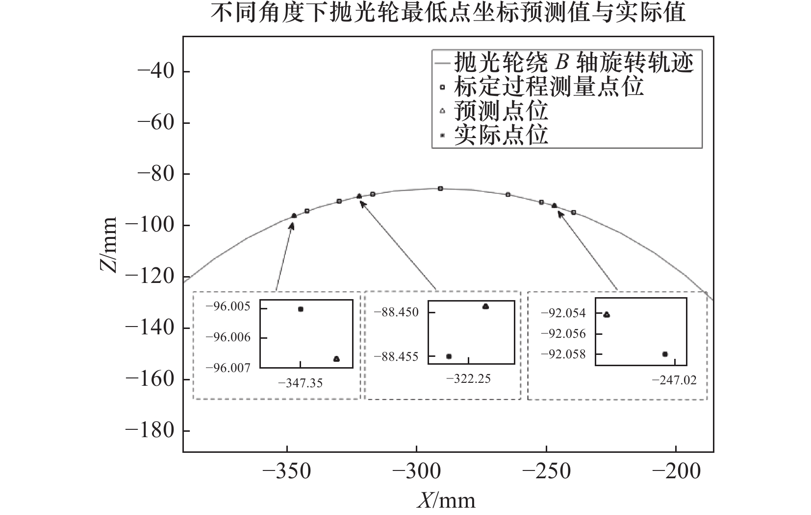
表 7 不同B轴角度下抛光轮X方向最低点坐标预测值与实际值
B/(°) 预测位置X/mm 实际位置X'/mm ΔX/mm 17 −247.029 4~
−247.023 8−247.021 0.002 8 −12 −322.250 7~
−322.244 9−322.252 −0.001 3 −22 −347.351 6~
−347.346 0−347.350 0
下载: 导出CSV
表 8 不同B轴角度下抛光轮Z方向最低点坐标预测值与实际值
B/(°) 预测位置Z/mm 实际位置Z'/mm ΔZ/mm 17 −92.055 2~
−92.053 2−92.058 −0.002 8 −12 −88.449 8~
−88.448 6−88.455 −0.005 2 −22 −96.007 8~
−96.005 6−96.005 0.000 6
下载: 导出CSV
-
[1] 江泽琦, 刘坪, 方建华. 磁流变液的研究综述[J]. 合成润滑材料, 2018, 45(2): 27-30. doi: 10.3969/j.issn.1672-4364.2018.02.010 [2] 王嘉琪, 肖强. 磁流变抛光技术的研究进展[J]. 表面技术, 2019, 48(10): 317-328. [3] 周静. 装夹误差及其主动控制方法研究[D]. 南京: 南京航空航天大学, 2011. [4] Barakat N A, Elbestawi M A, Spence A D. Kinematic and geometric error compensation of a coordinate measuring machine[J]. International Journal of Machine Tools and Manufacture, 2000, 40(6): 833-850. doi: 10.1016/S0890-6955(99)00098-X [5] 李亚康. 五轴数控机床精度检测与标定技术研究[D]. 沈阳: 沈阳工业大学, 2014. [6] 魏中兴, 吕彦明, 王发成, 等. 夹具静态误差与动态误差的综合分析[J]. 组合机床与自动化加工技术, 2012(5): 62-64,69. doi: 10.3969/j.issn.1001-2265.2012.05.017 [7] 杨航. 非球面磁流变抛光算法与实验研究[D]. 绵阳: 中国工程物理研究院, 2016. [8] 刘杰, 王飞, 简学之. 一种双摆头结构五轴数控机床RTCP标定及补偿方法: 中国, CN108334030B[P]. 2020-11-10. [9] 郑飂默, 于东, 张娜, 等. 一种基于AxiSet的五轴机床测量方法. 中国: CN105643362A[P]. 2016-06-08. [10] 郑立功, 李龙响, 王孝坤, 等. 磁流变抛光系统去除函数的原点位置标定[J]. 光学精密工程, 2017, 25(1): 8-14. [11] Ding D W, Zhao Z C, Li Y, et al. Calibration and capability assessment of on-machine measurement by integrating a laser displacement sensor[J]. The International Journal of Advanced Manufacturing Technology, 2021, 113: 2301-2313. doi: 10.1007/s00170-021-06676-5 [12] Zhao Z C, Ding D W, Fu Y C. Error identification and compensation for a laser displacement sensor based on on-machine measurement[J]. Optik, 2021, 225: 165902. doi: 10.1016/j.ijleo.2020.165902 [13] Ma X F, Cai Z Q, Yao B, et al. Analysis of factors affecting measurement accuracy and establishment of an optimal measurement strategy of a laser displacement sensor[J]. Applied Optics, 2020, 59(33): 10626. doi: 10.1364/AO.405554 [14] Guo Y X, Song B, Tang X Q, et al. A measurement method for calibrating kinematic parameters of industrial robots with point constraint by a laser displacement sensor[J]. Measurement Science and Technology, 2020, 31(7):075004 . [15] Wang Y Z, Liu J H, Chen H, et al. Orthogonality measurement of three-axis motion trajectories for micromanipulation robot systems[J]. Micromachines, 2021, 12(3): 344. doi: 10.3390/mi12030344 -

 下载:
下载:


 点击查看大图
图(8) / 表(8)
计量
- 文章访问数: 62
- HTML全文浏览量: 16
- PDF下载量: 78
- 被引次数: 0