Spatial error modeling and sensitivity analysis of ultra-precision micro-compound turn-milling machine tool
-
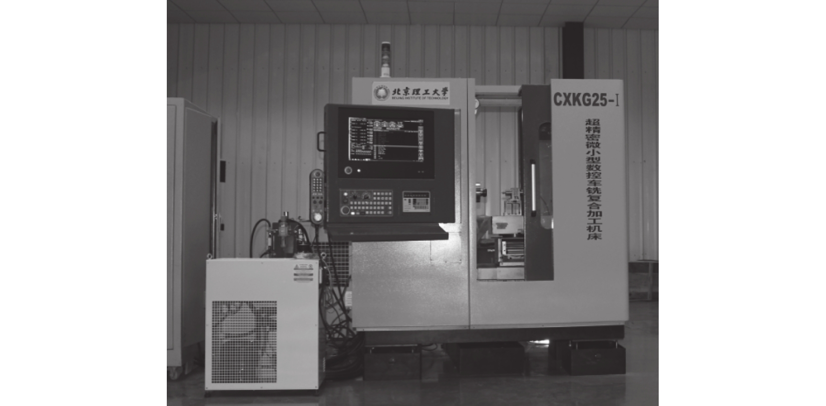
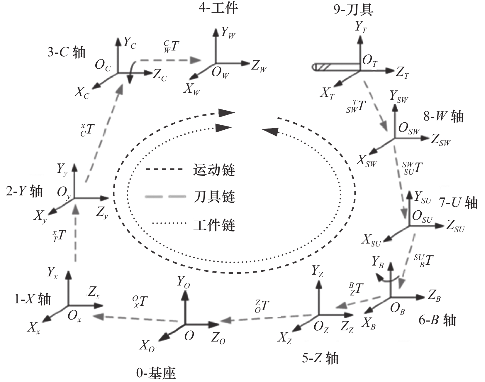
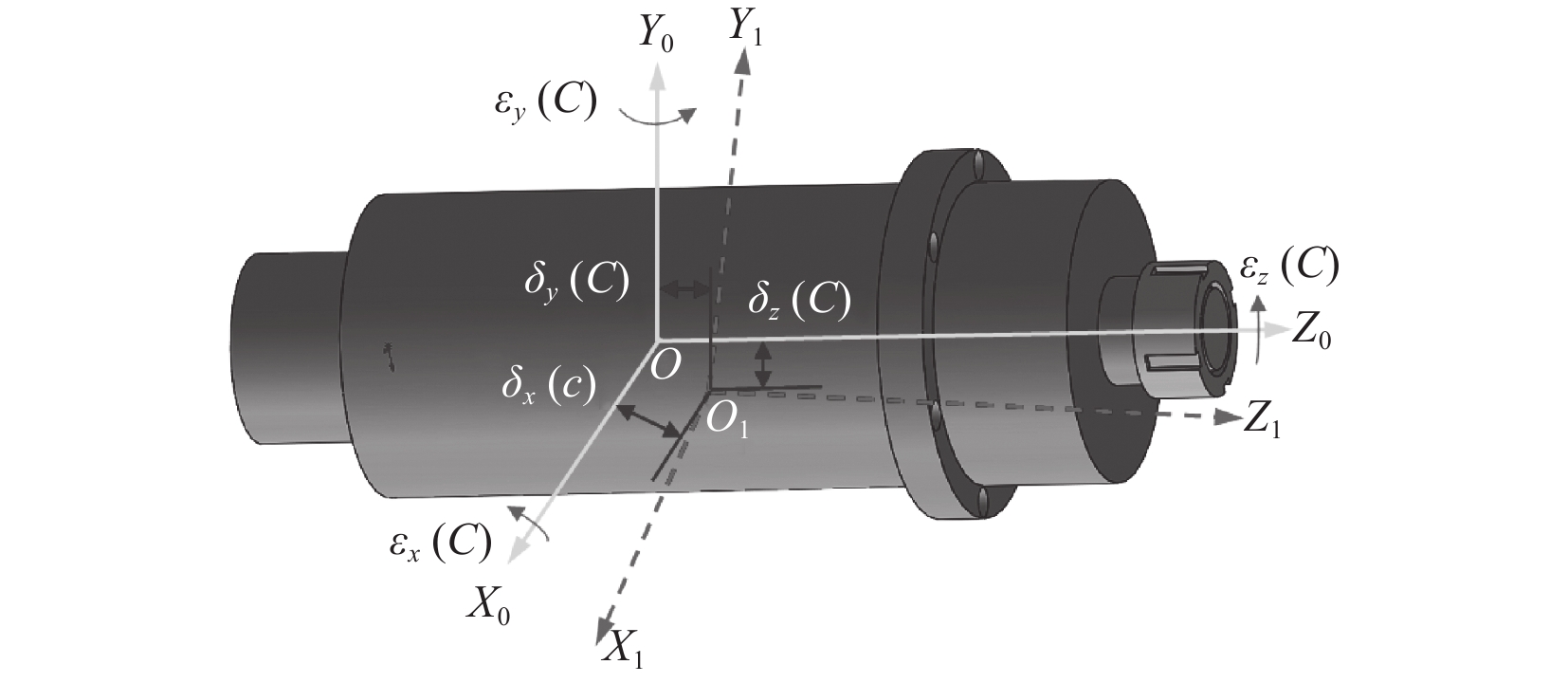
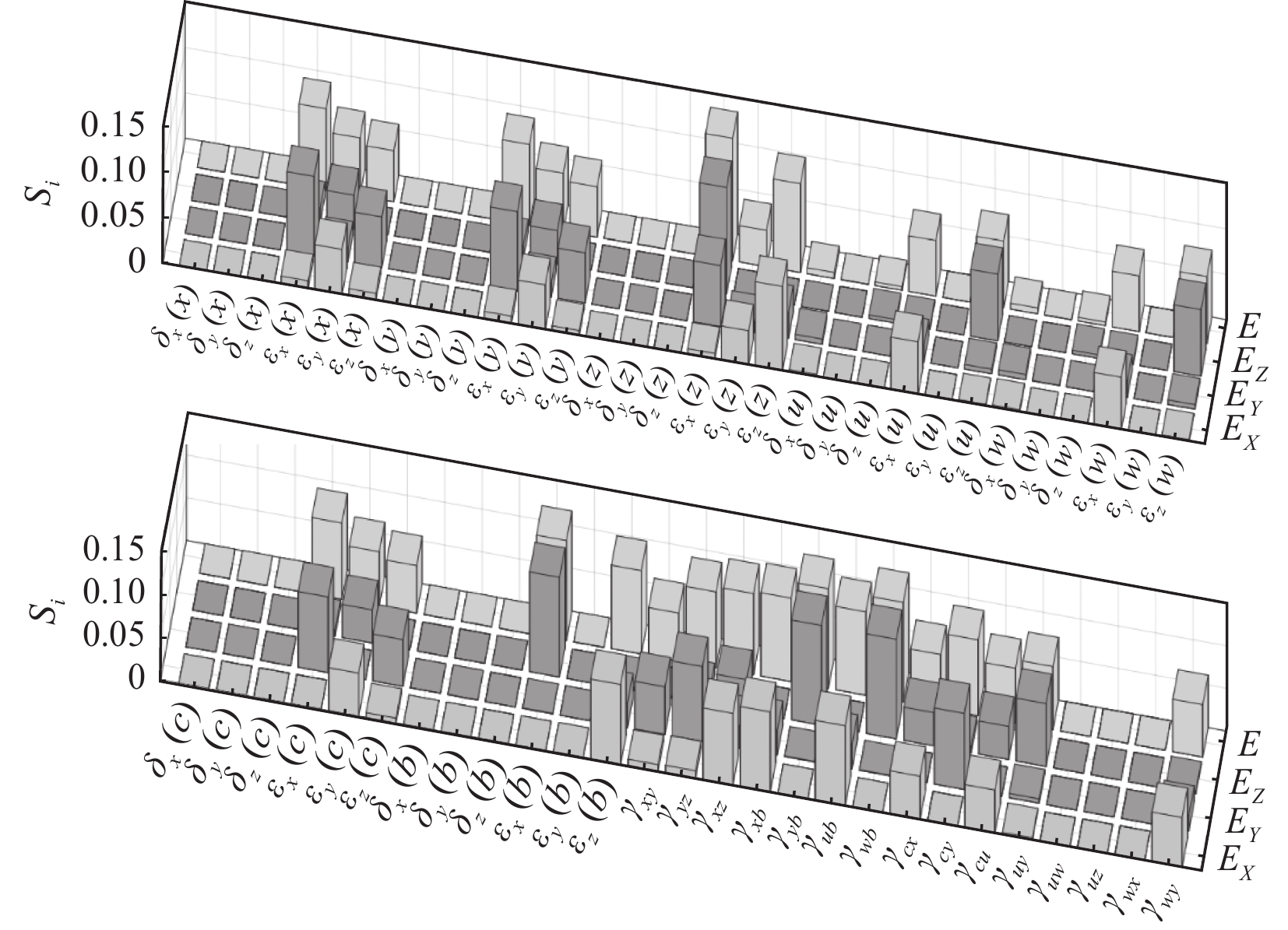
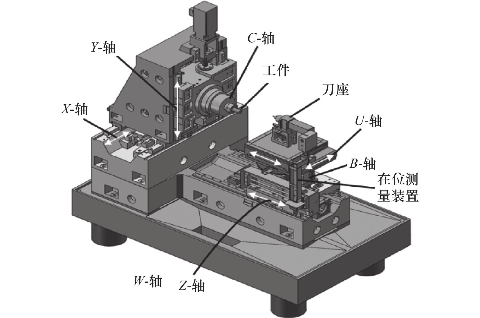
摘要: 微小型车铣复合加工机床可实现一次装夹完成大部分零件加工工序,是微小型复杂结构件加工必不可少的数控设备,作为精密加工数控设备,其自身的空间几何误差直接影响零件的加工精度。以北京理工大学自主研发的超精密微小型车铣复合加工机床CXKG25-I为研究对象,首先开展超精密车铣复合机床空间几何误差元素分析,获得机床的57项空间几何误差,并基于多体系统理论方法建立超精密车铣复合加工机床的空间几何误差模型。然后开展了空间几何误差因素的灵敏度分析,并揭示了影响机床加工误差的关键敏感因素,其分析结果指导和优化超精密车铣复合加工机床结构设计与制造。Abstract: The micro-compound turn-milling machine tool can complete most parts processing processes in one clamping process. It is an indispensable CNC equipment for processing micro complex structural parts. As a precision machining CNC equipment, its own spatial geometric error directly affects the machining accuracy of parts. The ultra-precision micro-compound turn-milling machine tool CXKG25-I developed by Beijing Institute of Technology was used as the research object in this paper. First, the spatial geometric error elements of the ultra-precision turn-milling compound machine tool were analyzed, and the 57 spatial geometric errors were obtained. The spatial geometric error model was established based on the multi-body system theory method. Then, the sensitivity analysis of the spatial geometric error project was carried out, and the key sensitive factors of machining errors were revealed. These analysis results guide and optimize the structural design and manufacturing of ultra-precision turn-milling machine tool.
-
表 1 超精密加工机床的几何误差元素
移动轴 运动误差 垂直度误差 X 轴 $ {\delta }_{x}\left(x\right) $, $ {\delta }_{y}\left(x\right) $, ${\delta }_{{\textit{z}}}\left(x\right)$, ${\varepsilon }_{x}\left(x\right)$, $ {\varepsilon }_{y}\left(x\right) $, ${\varepsilon }_{{\textit{z}}}\left(x\right)$ $ {\gamma }_{xy} $ Y 轴 $ {\delta }_{x}\left(y\right) $, $ {\delta }_{y}\left(y\right) $, ${\delta }_{{\textit{z}}}\left(y\right)$, $ {\varepsilon }_{x}\left(y\right) $, $ {\varepsilon }_{y}\left(y\right) $, ${\varepsilon }_{{\textit{z}}}\left(y\right)$ ${\gamma }_{y{\textit{z}}}$ Z 轴 ${\delta }_{x}\left({\textit{z}}\right)$, ${\delta }_{y}\left({\textit{z}}\right)$, ${\delta }_{{\textit{z}}}\left({\textit{z}}\right)$, ${\varepsilon }_{x}\left({\textit{z}}\right)$, ${\varepsilon }_{y}\left({\textit{z}}\right)$, ${\varepsilon }_{{\textit{z}}}\left({\textit{z} }\right)$ ${\gamma }_{x{\textit{z}}}$ B 轴 $ {\delta }_{x}\left(\beta \right) $, $ {\delta }_{y}\left(\beta \right) $, ${\delta }_{{\textit{z}}}\left(\beta \right)$, $ {\varepsilon }_{x}\left(\beta \right) $, $ {\varepsilon }_{y}\left(\beta \right) $, ${\varepsilon }_{{\textit{z}}}\left(\beta \right)$ $ {\gamma }_{xb} $, ${\gamma }_{{\textit{z}}b}$, $ {\gamma }_{ub} $, $ {\gamma }_{wb} $ C 轴 $ {\delta }_{x}\left(c\right) $, $ {\delta }_{y}\left(c\right) $, ${\delta }_{{\textit{z}}}\left(c\right)$, $ {\varepsilon }_{x}\left(c\right) $, $ {\varepsilon }_{y}\left(c\right) $, ${\varepsilon }_{{\textit{z}}}\left(c\right)$ $ {\gamma }_{cx} $, $ {\gamma }_{cy} $, $ {\gamma }_{cu} $ U 轴 $ {\delta }_{x}\left(u\right) $, $ {\delta }_{y}\left(u\right) $, ${\delta }_{{\textit{z}}}\left(u\right)$, $ {\varepsilon }_{x}\left(u\right) $, $ {\varepsilon }_{y}\left(u\right) $, ${\varepsilon }_{{\textit{z}}}\left(u\right)$ $ {\gamma }_{uy} $, $ {\gamma }_{uw} $, ${\gamma }_{u{\textit{z}}}$ W 轴 $ {\delta }_{x}\left(w\right) $, $ {\delta }_{y}\left(w\right) $, ${\delta }_{{\textit{z}}}\left(w\right)$, $ {\varepsilon }_{x}\left(w\right) $, $ {\varepsilon }_{y}\left(w\right) $, ${\varepsilon }_{{\textit{z}}}\left(w\right)$ $ {\gamma }_{wx} $, $ {\gamma }_{wy} $  下载: 导出CSV
表 3 超精密车铣复合加工机床各种间初始参考位置
位置参数 数值/mm $ {{p}_{0x},p}_{1x} $,$ {p}_{2x} $,$ {p}_{3x} $,$ {p}_{4x} $,$ {p}_{5x} $,$ {p}_{6x} $,$ {p}_{7x} $,$ {p}_{8x} $ 481, –335.5, 0, 0, 0, 0, 0, 0, 0 $ {p}_{0y},{p}_{1y} $,$ {p}_{2y} $,$ {p}_{3y} $,$ {p}_{4y} $,$ {p}_{5y} $,$ {p}_{6y} $,$ {p}_{7y} $,$ {p}_{8y} $ –92.995, 518, 0, 0, 0, 0, –184.901, 0, –309 ${p}_{0{\textit{z}}},{p}_{1{\textit{z}}}$,${p}_{2{\textit{z}}}$,${p}_{3{\textit{z}}}$,${p}_{4{\textit{z}}}$,${p}_{5{\textit{z}}}$,${p}_{6{\textit{z}}}$,${p}_{7{\textit{z}}}$,${p}_{8{\textit{z}}}$ –629.002, 164.0028, 0, 0,
286, 0, 0, 0, 0
下载: 导出CSV
-
[1] 周宝仓. 大型数控成形磨齿机几何误差理论及补偿方法研究[D]. 重庆: 重庆大学, 2017. [2] Schultschik R. The components of the volumetric accuracy[J]. A CIRP, 1977, 26(1): 223-226. [3] 刘又午, 刘丽冰, 赵小松, 等. 数控机床误差补偿技术研究[J]. 中国机械工程, 1998, 17(12): 48-52. [4] 张宏韬, 杨建国, 姜辉, 等. 双转台五轴数控机床误差实时补偿[J]. 机械工程学报, 2010, 46(21): 143-148. [5] Chen J S, Ling C C. Improving the machine accuracy through machine tool metrology and error correction[J]. The International Journal of Advanced Manufacturing Technology, 1996, 11(3): 198-205. doi: 10.1007/BF01351325 [6] 项四通. 五轴数控机床空间误差测量, 建模与补偿技术研究[D]. 上海: 上海交通大学, 2016. [7] 范晋伟, 吕琦. 复合数控机床几何误差建模及灵敏度分析[J]. 制造技术与机床, 2017(3): 69-73. [8] 李二波. 高精度微小型车铣复合加工机床静动态性能研究[D]. 北京: 北京理工大学, 2017. [9] 徐立勋. 基于零件精度的超精密五轴机床误差建模与灵敏度分析[D]. 哈尔滨: 哈尔滨工业大学, 2017. [10] Lee K I, Yang S H. Robust measurement method and uncertainty analysis for position-independent geometric errors of a rotary axis using a double ball-bar[J]. International Journal of Precision Engineering and Manufacturing, 2013, 14(2): 231-239. doi: 10.1007/s12541-013-0032-z [11] 付国强. 基于指数积理论和坐标系微分运动关系的数控机床几何误差建模与补偿方法研究[D]. 杭州: 浙江大学, 2016. [12] Liu X, Zhang X, Fang F, et al. Identification and compensation of main machining errors on surface form accuracy in ultra-precision diamond turning[J]. International Journal of Machine Tools and Manufacture, 2016, 105: 45-57. doi: 10.1016/j.ijmachtools.2016.03.001 [13] 邓勇军. 高精度微小型车铣复合加工机床误差建模与补偿研究[D]. 北京: 北京理工大学, 2015. -

 下载:
下载:


 点击查看大图
图(9) / 表(3)
计量
- 文章访问数: 86
- HTML全文浏览量: 23
- PDF下载量: 79
- 被引次数: 0