Research on NC machining technology of thin-walled aluminum alloy box parts
-
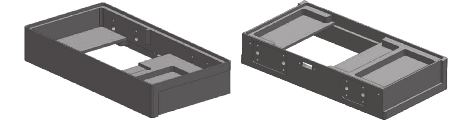
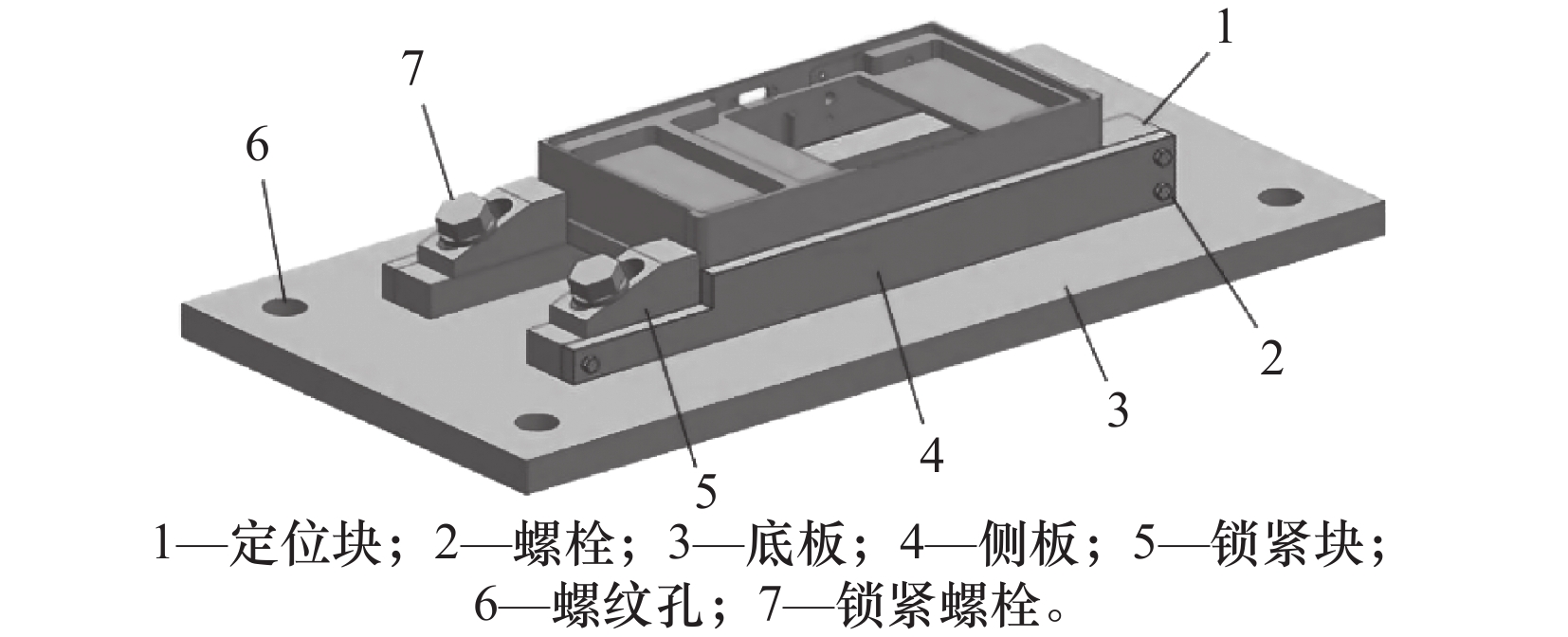
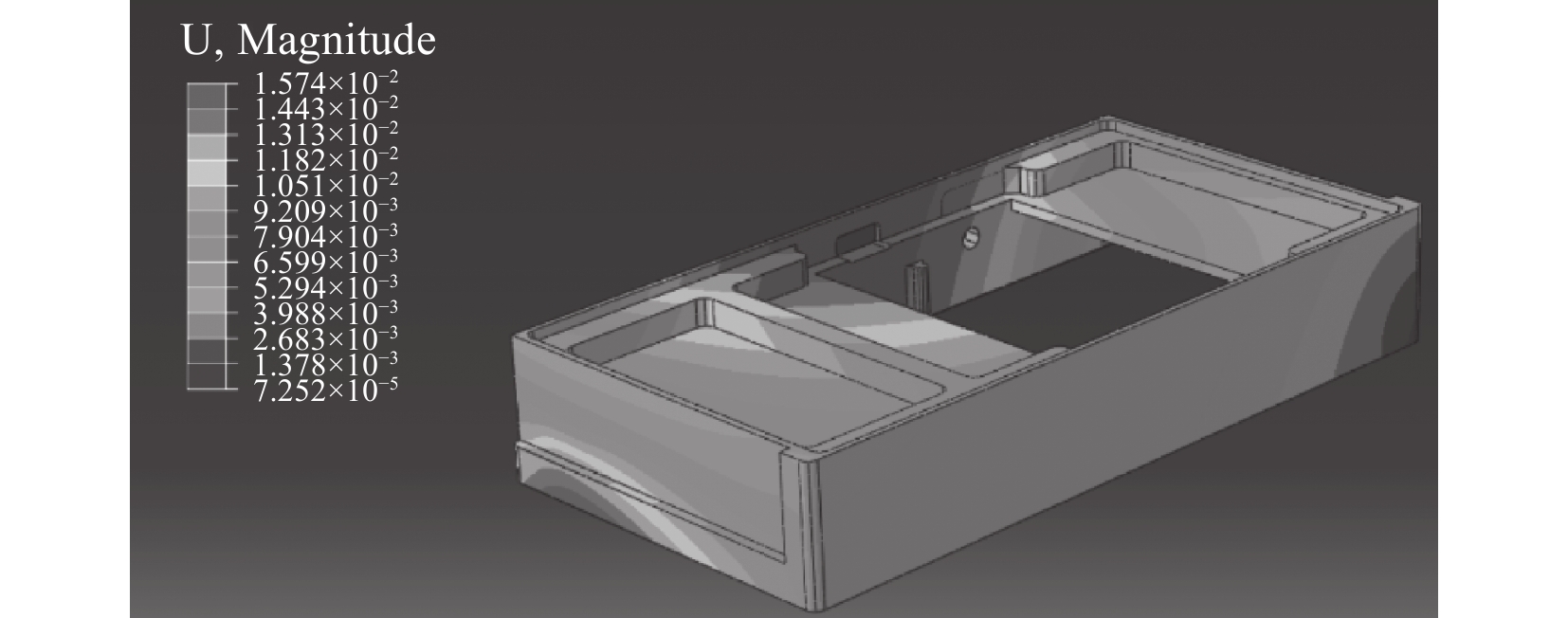
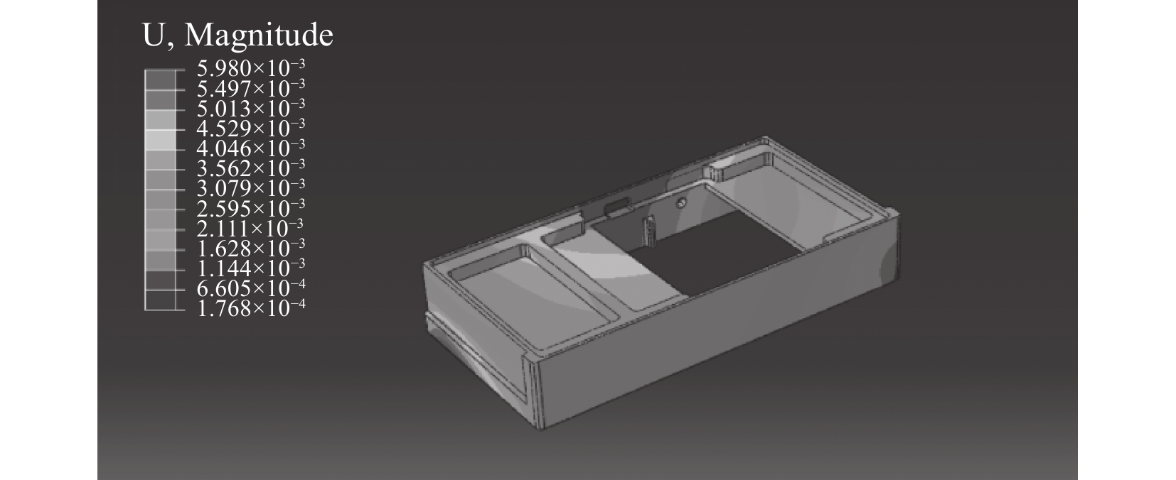
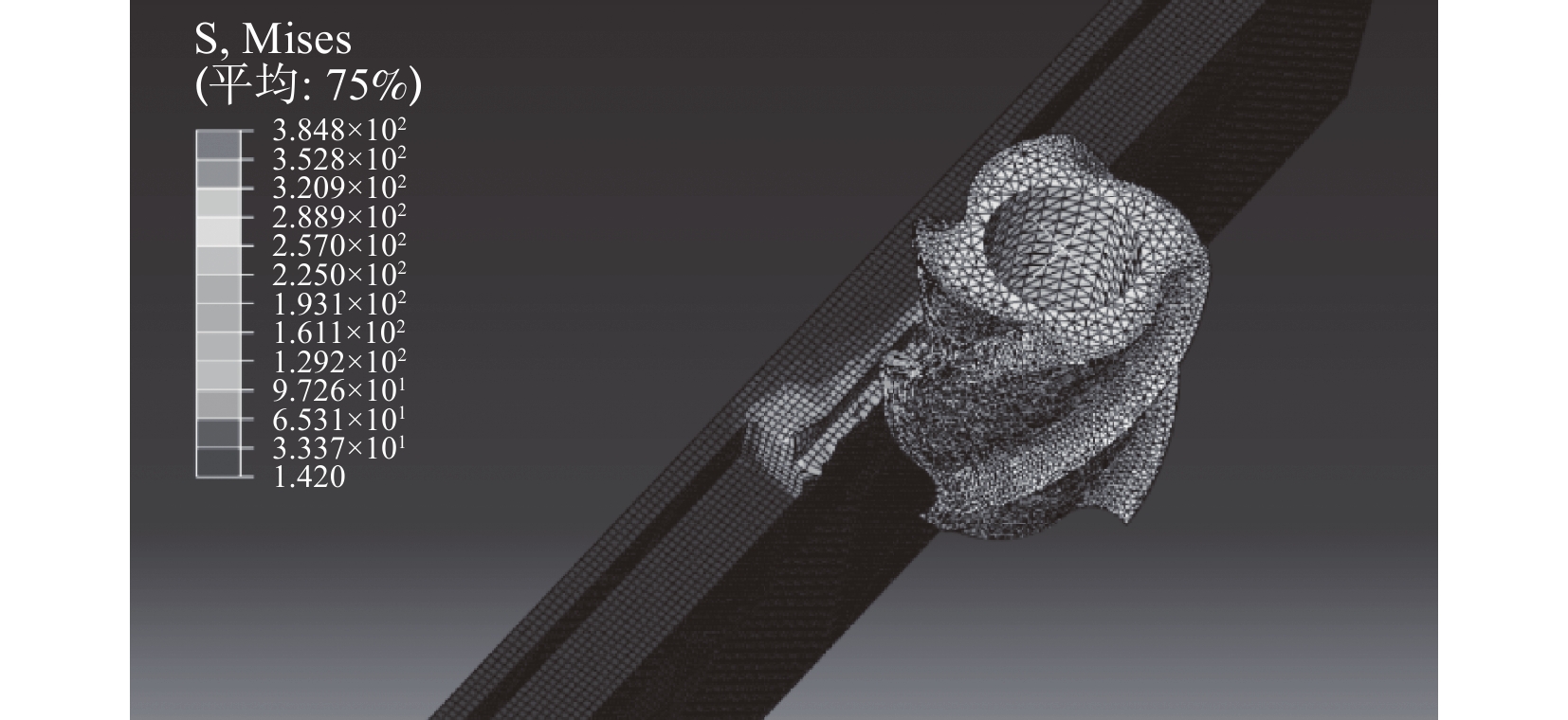
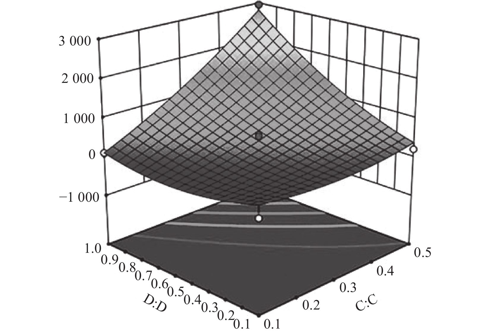
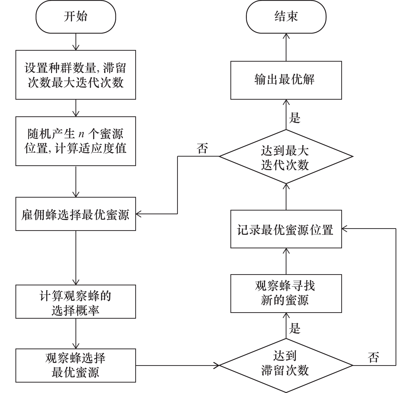
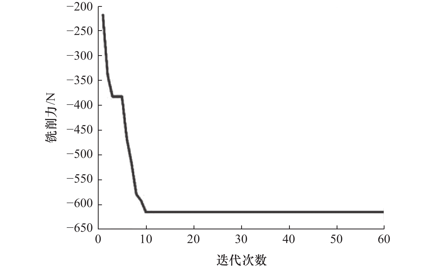
摘要: 针对某薄壁铝合金箱体零件因侧壁过薄易装夹变形与铣削变形导致精度降低的问题,设计了专用夹具并进行有限元分析,使装夹变形量从0.015 7 mm减小到0.005 98 mm,减小了61.9%;通过Design-Expert软件建立参数样本并生成目标函数,采用人工蜂群算法对目标函数进行优化,获取了一组铣削合力最小的铣削参数组合并输出预测值,利用ABAQUS软件对所输出参数进行仿真模拟,使铝合金薄壁箱体的铣削合力减小了35.3%;最后进行了实际加工实验,对零件尺寸进行测量,均符合公差范围。研究表明该方法对薄壁铝合金箱体零件提高加工尺寸精度有重要意义。Abstract: The problem of thin-walled aluminum alloy box parts due to thin side walls and milling deformation caused by the reduction of accuracy. A special fixture was designed and finite element analysis was performed, and the clamping deformation was reduced from 0.015 7 mm to 0.005 98 mm, a reduction of 61.9%; parameter samples were created and objective functions were generated by Design-Expert software, and an artificial bee colony algorithm was used to optimize the objective functions, and a set of milling parameters with the minimum milling force was obtained and the predicted values were output. ABAQUS software was used to simulate the output parameters, and the optimized results reduced the milling force of the thin-walled aluminum alloy box by 35.3%; finally, the actual machining experiments were conducted, and the dimensions of the parts were measured to be within the tolerance range. The study shows that the method is important for the thin-walled box parts to improve the machining dimensional accuracy.
-
表 1 零件尺寸测量结果
mm 序号 基本尺寸 测量尺寸 公差 符合 1 140 144.13 +0.4;−0.2 否 2 63.5 63.16 +0.4;−0.2 否 3 70 70.54 +0.4;−0.2 否 4 28 28.04 +0.1;0 是 5 40.5 40.55 +0.2;0 是 6 50.5 50.52 +0.2;0 是 7 13 12.93 +0.2;0 否 8 31 31.06 +0.1;0 是 9 47 47.04 +0.1;0 是 10 126 126.08 $ \text{±0.05} $ 否 11 110 110.12 $ \text{±0.1} $ 否  下载: 导出CSV
表 3 铣削刀具和薄壁件的材料属性
密度/
(kg/m3)弹性模量/
GPa泊松比 比热容/
(J/kg·k)热膨胀系数/
(×10-6/ºC)铣刀 7 780 600 0.25 950 4.5 薄壁件 2 780 71 0.3 921 22.3
下载: 导出CSV
表 6 可控因素及水平
水平 主轴转速/
(r/min)进给速度/
(mm/min)径向切深/
mm轴向切深/
mm1 1500 400 0.1 0.1 2 2250 600 0.3 0.5 3 3000 800 0.5 1
下载: 导出CSV
表 7 铣削加工参数仿真结果
序号 主轴转速/
(r/min)进给速度/
(mm/min)径向切深/
mm轴向切深/
mm铣削力/
N1 1 500 600 0.5 0.55 1 180 2 2 250 600 0.3 0.55 600 3 3 000 600 0.5 0.55 1 390 4 1 500 400 0.3 0.55 606 5 3 000 600 0.1 0.55 75.5 6 2 250 800 0.1 0.55 57.7 7 1 500 600 0.3 1 1 300 8 2 250 600 0.5 0.1 216 9 2 250 600 0.1 0.1 21.2 10 2 250 600 0.1 1 122 11 2 250 400 0.3 1 1 680 12 3 000 600 0.3 0.1 59.7 13 2 250 600 0.3 0.55 290 14 1 500 600 0.1 0.55 69.4 15 2 250 600 0.3 0.55 340 16 2 250 400 0.5 0.55 1 980 17 3 000 800 0.3 0.55 308 18 3 000 400 0.3 0.55 652 19 2 250 800 0.3 0.1 47.1 20 1 500 800 0.3 0.55 267 21 2 250 800 0.5 0.55 921 22 1 500 600 0.3 0.1 1 230 23 3 000 600 0.3 1 1 320 24 2 250 600 0.5 1 2 950 25 2 250 600 0.3 0.55 397 26 2 250 800 0.3 1 888 27 2 250 600 0.3 0.55 550 28 2 250 400 0.3 0.1 80.4 29 2 250 400 0.1 0.55 102
下载: 导出CSV
表 8 铣削力回归方程模型方差分析
来源 平方和 自由度 F值 P值 显著性 模型 13 070 000.00 14 13.45 < 0.000 1 显著 A-A 59 812.32 1 0.86 0.37 B-B 568 400.00 1 8.19 0.01 C-C 5 589 000.00 1 80.49 < 0.000 1 D-D 3 636 000.00 1 52.37 < 0.000 1 AB 6.25 1 0.00 0.99 AC 10 393.80 1 0.15 0.70 AD 354 200.00 1 5.10 0.04 BC 257 400.00 1 3.71 0.07 BD 143 900.00 1 2.07 0.17 CD 1733 000.00 1 24.97 0.00 A² 77 597.13 1 1.12 0.31 B² 4.41 1 0.00 0.99 C² 228 700.00 1 3.29 0.09 D² 551 100.00 1 7.94 0.01 $ {R}^{2} $ 93.08%
下载: 导出CSV
表 9 优化前后铣削加工数据
主轴转速/
(r/min)进给速度/
(mm/min)径向切深/
mm轴向切深/
mm铣削力/N 优化前 1500 600 0.5 0.5 1032.794 优化后 3000 800 0.5 0.1 668.289
下载: 导出CSV
表 10 加工刀具卡
mm 编号 刀具名称 刀位号 直径 长度 刃长 1 立铣刀 T01 10 72 22 2 立铣刀 T02 4 43 11 3 立铣刀 T03 2 40 7 4 立铣刀 T04 1 40 2 5 麻花钻 T05 4 55 22 6 麻花钻 T06 2 38 12
下载: 导出CSV
表 12 测量结果
mm 基本尺寸 优化后尺寸 公差 符合 140 140.12 +0.4;−0.2 是 126 126.03 $ \text{±0.05} $ 是 110 110.08 $ \text{±0.1} $ 是 63.5 63.66 +0.4;−0.2 是 70 69.90 +0.4;−0.2 是 13 13.11 +0.2;0 是
下载: 导出CSV
表 11 加工工序卡
工步 工步内容 刀具号 刀具
规格/
mm主轴
转速/
(r/min)进给
速度/
(mm/min)径向
切深/
mm轴向
切深/
mm1 光整正面 T01 ϕ10 3000 1500 0.5 0.1 以正面为
基准2 粗铣反面
各平面T01 ϕ10 1500 800 1 1 3 精铣反面
各平面T02 ϕ4 3000 800 0.5 0.1 4 精铣反面
轮廓T04 ϕ1 2000 600 0.5 0.1 以反面为
基准5 粗铣正面
各平面T01 ϕ10 1500 800 1 1 6 精铣正面
各平面T02 ϕ4 3000 800 0.5 0.1 7 加工正面R2
圆角T03 ϕ2 2000 400 0.5 0.1 8 精铣正面
轮廓T04 ϕ1 2000 600 0.5 0.1 侧面定位 9 粗铣侧面 T02 ϕ4 1500 800 1 0.5 10 精铣侧面 T03 ϕ2 2000 600 0.5 0.1 11 粗铣侧面
矩形槽T03 ϕ2 1500 800 1 0.5 12 精铣侧面
矩形槽T04 ϕ1 2000 600 0.5 0.1 13 钻4-ϕ4 T05 ϕ4 2000 400 14 钻12-ϕ2 T06 ϕ2 1000 100
下载: 导出CSV
-
[1] Tian C L,Zhou G H,Zhang J J,et al. Optimization of cutting parameters considering tool wear conditions in low-carbon manufacturing environment[J]. Journal of Cleaner Production,2019,226:706-719. doi: 10.1016/j.jclepro.2019.04.113 [2] 高翔,张连文,王勇. 薄壁零件装夹方案设计与优化[J]. 组合机床与自动化加工技术,2009(6):9-12. [3] 马广. 铝合金薄壁零件数控加工夹具问题探讨[J]. 制造技术与机床,2014(11):71-75. doi: 10.3969/j.issn.1005-2402.2014.11.024 [4] 赵旭芳,梁昔明. 改进的人工蜂群算法及其在参数优化中的应用[J]. 计算机仿真,2019,36(9):320-325. [5] 宋娟,倪志伟,李萍,等. 基于参数优化深度置信网络的雾霾预测模型[J]. 系统科学与数学,2020,40(9):1644-1661. [6] Pholdee N,Bureerat S. Comparative performance of meta-heuristic algorithms for mass minimisation of trusses with dynamic constraints[J]. Advances in Engineering Software,2014,75:1-13. doi: 10.1016/j.advengsoft.2014.04.005 [7] 王立涛,柯映林,黄志刚. 航空铝合金7050-T7451铣削力模型的实验研究[J]. 中国机械工程,2003,14(19):1684-1686. [8] 杨叔子, 李斌, 张福润, 等. 机械加工工艺师手册[M]. 2版. 北京: 机械工业出版社, 2012: 300-305. [9] 王鑫. 铝合金共形件铣削加工仿真及切削参数优化关键技术研究[D]. 成都: 四川大学, 2021. [10] 董如意,孙立勋. 基于改进人工蜂群优化算法的PID参数整定[J]. 吉林化工学院学报,2022,39(5):73-76. -

 下载:
下载:

 点击查看大图
图(11) / 表(12)
计量
- 文章访问数: 150
- HTML全文浏览量: 22
- PDF下载量: 40
- 被引次数: 0