A grinding wheel wear calculation and trajectory adjustment algorithm for helical groove grinding process
-
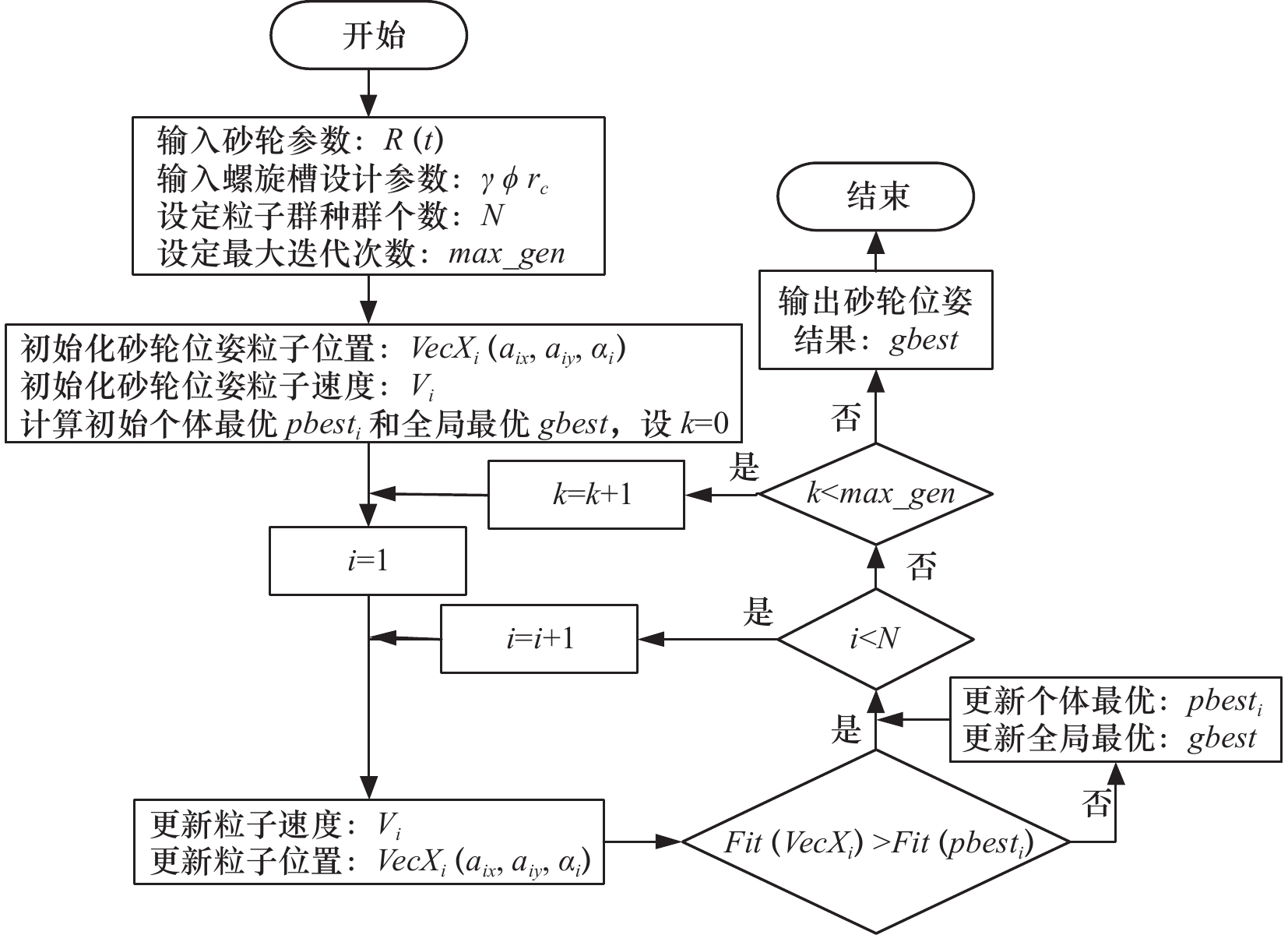
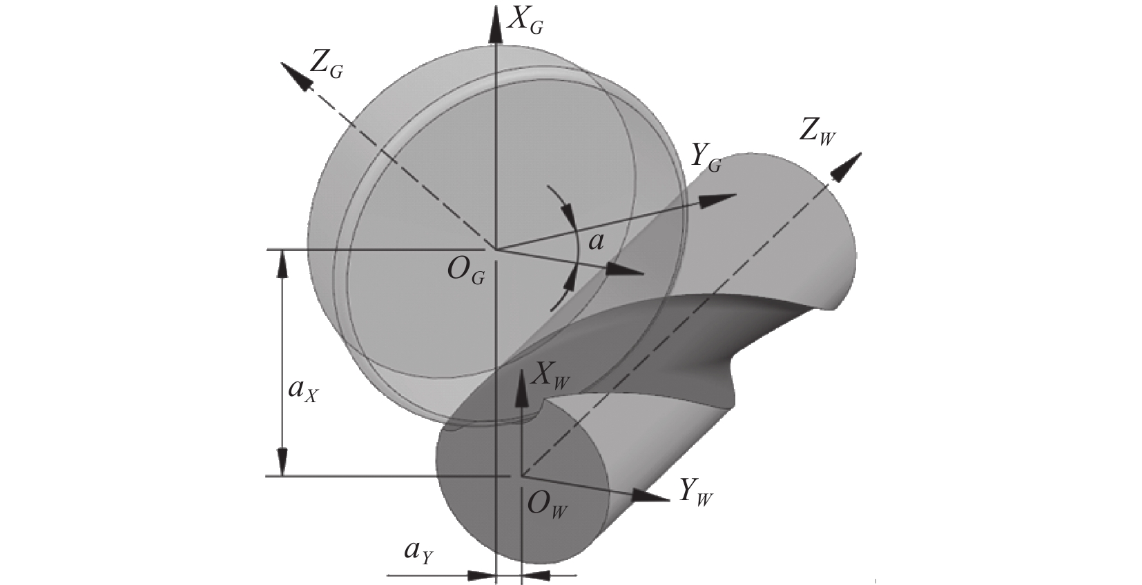
摘要: 立铣刀螺旋槽具有结构多样、精度高等特点,在切削加工中对刀具的切削和排屑都起到了重要的作用,而在立铣刀螺旋槽磨削过程中,由于砂轮的磨损会导致螺旋槽的磨削精度降低,且砂轮的磨损具有不规则性,很难预测砂轮磨损后形状,因此文章针对在砂轮出现磨损后,提出计算磨损砂轮轮廓的方法以及砂轮实际磨损情况的磨削位姿补偿算法。首先,建立螺旋槽磨削过程中砂轮与刀具棒料的运动学模型,并通过补偿前加工的螺旋槽实测轮廓反算出磨损砂轮轮廓;其次,应用解析法重新构建磨损砂轮磨削的螺旋槽形成计算模型;然后,根据螺旋槽前角、芯厚、槽宽等结构参数定义,建立螺旋槽结构参数关于磨损砂轮位姿函数关系式,并通过优化算法进行砂轮位姿补偿求解;最后,通过仿真与实际加工试验,对比分析磨损砂轮位姿补偿前后加工精度,验证算法的有效性。Abstract: The helical groove has the characteristics of various structures and high precision requirements, which play an important role in cutting and chip removal. In the grinding process of the helical groove, the grinding accuracy is reduced due to the grinding wheel wear, and the wear is irregular, so it is difficult to predict the grinding wheel profile after wear. Aiming this issue, a calculation method of the wear grinding wheel profile and a grinding trajectory adjustment algorithm based on the actual wear of the grinding wheel are proposed. Firstly, the actual measurement of the wear of the grinding wheel is carried out, and the mathematical model of the movement relationship between the grinding wheel and the tool bar during the spiral groove grinding process is established. Secondly, the curve equation of the radial cross-section profile of the groove. Then, according to the definition of the spiral groove rake angle, core thickness, groove width and other parameters, establish the functional relationship of the grinding wheel position and posture, convert the trajectory compensation calculation of the worn grinding wheel into a mathematical optimization problem, and the bionic optimization algorithm is used to solve the problem quickly. Finally, through a series of simulation and actual machining experiments, the accuracy and adaptability of the algorithm are analyzed to verify the effectiveness of the algorithm.
-
Key words:
- helical groove /
- grinding position and orientation /
- grinding wheel wear /
- compensation
-
表 1 螺旋槽设计和磨削工艺初始参数
螺旋槽设计参数 砂轮几何参数 调整前砂轮安装位姿 R= 6 mm
β= 45°
γ= 10°
rc= 3.5 mm
ϕ= 110°砂轮半径Rg=61.5 mm
砂轮厚度Hg=10 mm
砂轮锥度κg=90°
圆弧半径rg=1.0 mmax= 61.134 7 mm
ay=−16.504 6 mm
α= 43.018 4° 下载: 导出CSV
表 2 磨损砂轮位姿调整前磨削的螺旋槽轮廓点坐标测量值
序号 XW YW 序号 XW YW 序号 XW YW 1 6.0000 0.0000 12 3.5203 1.9199 23 1.7160 4.8226 2 5.6828 −0.0177 13 3.4420 2.2276 24 1.7160 4.8226 3 5.3656 −0.0064 14 3.3578 2.5337 25 1.4628 5.0141 4 5.0517 0.0385 15 3.2513 2.8326 26 1.1989 5.1904 5 4.7565 0.1534 16 3.1188 3.1210 27 0.9238 5.3487 6 4.4879 0.3220 17 2.9659 3.3992 28 0.6383 5.4875 7 4.2529 0.5347 18 2.7955 3.6669 29 0.3445 5.6076 8 4.0474 0.7767 19 2.6086 3.9235 30 0.0443 5.7107 9 3.8630 1.0348 22 2.4061 4.1680 31 −0.2603 5.8000 10 3.7193 1.3176 21 2.1890 4.3995 32 −0.5676 5.8799 11 3.6090 1.6151 22 1.9584 4.6177 33 −0.8800 5.9351
下载: 导出CSV
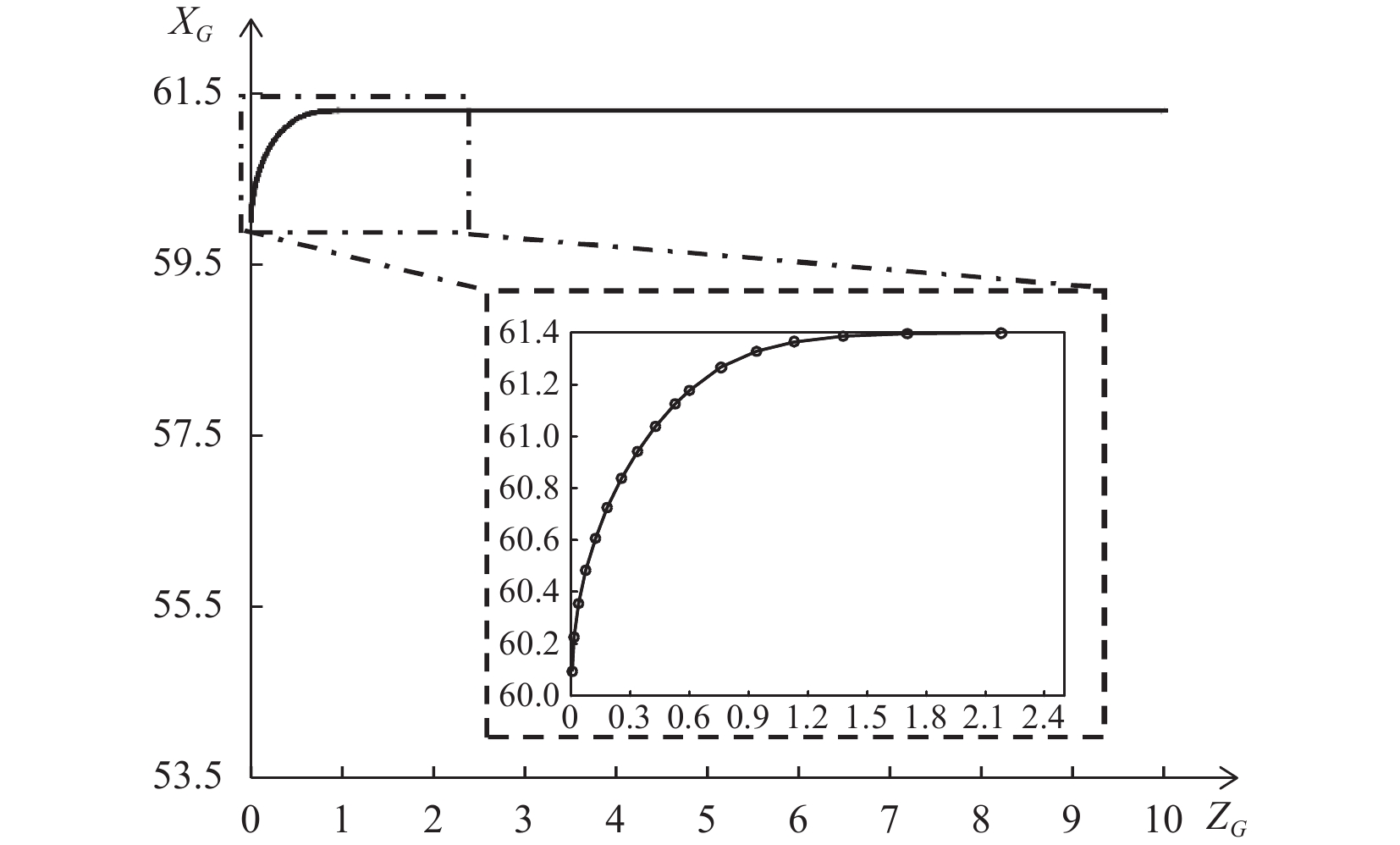
表 3 反算得到的磨损砂轮轮廓点坐标值
序号 XG ZG 序号 XG ZG 序号 XG ZG 1 59.5885 0.0004 12 61.3092 0.9569 23 61.3987 2.9105 2 59.7674 0.0101 13 61.3616 1.1631 24 61.3983 3.1341 3 59.9453 0.0326 14 61.3857 1.4280 25 61.3988 3.3513 4 60.1210 0.0679 15 61.3944 1.7387 26 61.3992 3.5411 5 60.2937 0.1157 16 61.3955 1.8168 27 61.3971 3.7128 6 60.4626 0.1758 17 61.3961 1.9234 28 61.3965 3.9367 7 60.6267 0.2479 18 61.3965 2.1231 29 61.3969 4.1642 8 60.7851 0.3317 19 61.3963 2.3013 30 61.3977 4.4126 9 60.8989 0.4091 22 61.4011 2.4612 31 61.3974 4.7356 10 61.0726 0.5838 21 61.4012 2.6023 32 61.3975 5.0238 11 61.2164 0.7712 22 61.4014 2.7704 33 −61.3977 5.3971
下载: 导出CSV
表 4 算法参数设置
算法参数设置 搜索空间 调整后的砂轮位姿 C1/ C1=1.5
ω=0.6
N=50
ε1=0.9, ε2=0.9, ε3=0.8ax =[57.1347, 61.1347]
ay=[-17.4227, -14.4227]
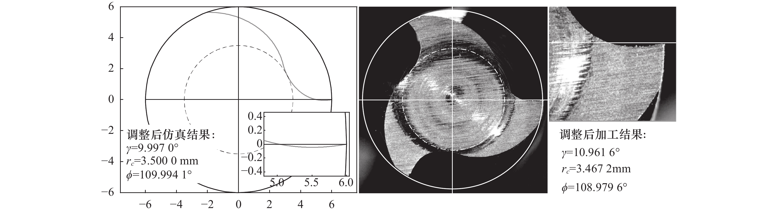
α= [43.0184, 45]ax= 60.2164 mm
ay= -16.5560 mm
α= 45.2609°
下载: 导出CSV
-
[1] 李国超,孙杰. 整体式立铣刀刃磨仿真技术研究现状与发展趋势[J]. 机械工程学报,2015,51(9):165-175. [2] He L L ,Wang X B ,Liu Z B ,et al. Mathematical modeling and parametric design of taper end mills[J]. Advanced Materials Research,2013,797:574-578. [3] Wang W P ,Wang K K . Geometric modeling for swept volume of moving solids[J]. Computer Graphics & Applications IEEE,1986,6(12):8-17. [4] Nguyen V H ,Ko S L . Determination of workpiece profile and influence of singular point in helical grooving[J]. CIRP Annals - Manufacturing Technology,2013,62(1):323-326. [5] Li G C,Jie S ,Li J F . Modeling and analysis of helical groove grinding in end mill machining[J]. Journal of Materials Processing Technology,2014,214(12):3067-3076. [6] Kim J H ,Park J W ,Ko T J . End mill design and machining via cutting simulation[J]. Computer-Aided Design,2008,40(3):324-333. [7] Karpuschewski B ,Jandecka K ,Mourek D . Automatic search for wheel position in flute grinding of cutting tools[J]. CIRP Annals - Manufacturing Technology,2011,60(1):347-350. [8] 李国超,周宏根,景旭文,等. 基于小生境粒子群算法的刀具容屑槽刃磨工艺设计[J]. 计算机集成制造系统,2019(7):1746-1756. [9] 李海宾,王成兵,马玉豪,等. 一种粗铣刀周齿分屑槽的数控磨削工艺算法[J/OL]. 机械科学与技术:1-62023-04-04].https://doi.org/10.13433/j.cnki.1003-8728.20220071. [10] 曾滔,刘战强,左小陈,等. 刀具螺旋槽磨削接触线的几何求解及其在三维建模中的应用[J]. 制造技术与机床,2021(7):43-48. [11] Chen Z ,Liu X L,He G H,et al. An iteration-based algorithm for two-pass flute grinding of slide round milling tools[J]. The International Journal of Advanced Manufacturing Technology,2020,111:2533-2543. [12] 唐军,马忠宝,宁样城,等. 整体式立铣刀端齿分屑槽的磨削轨迹算法研究[J]. 制造技术与机床,2021(6):65-70. [13] 熊建军,李海宾,王成兵,等. 钻尖容屑槽的砂轮磨削位姿算法研究[J]. 工具技术,2022,56(3):92-96. -

 下载:
下载:

 点击查看大图
图(14) / 表(4)
计量
- 文章访问数: 94
- HTML全文浏览量: 9
- PDF下载量: 24
- 被引次数: 0