Optimisation of the column structure of a small drilling machine based on reverse engineering
-
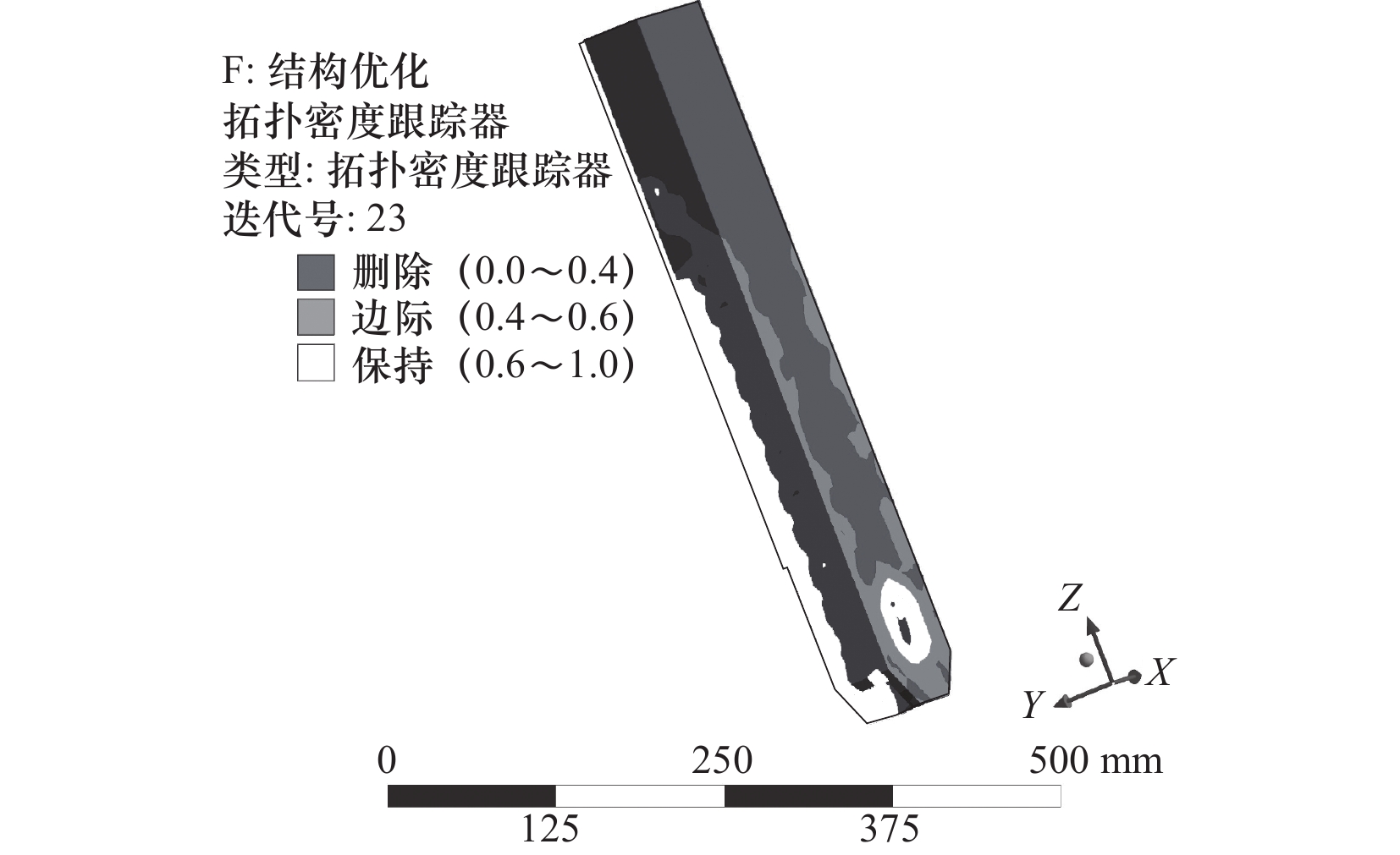
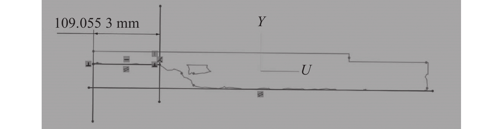
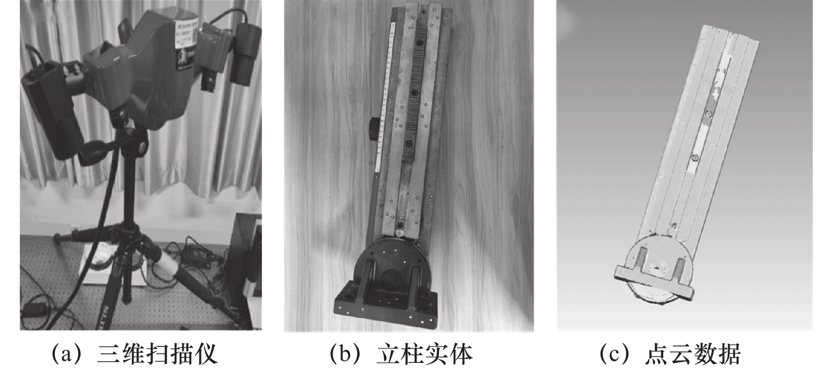
摘要: 立柱的结构性能是机床工作稳定的关键。为了满足在减轻立柱质量的同时提高其动静态特性,文章从机床结构模型获取出发,通过三维扫描采集机床零部件点云数据,然后利用逆向建模技术将其转换为实体模型,再使用有限元仿真求解立柱的关键性指标并完成优化。在模型获取方面,使用2D分析比较立柱实体外轮廓与点云数据偏差,测得整体平均偏差为−0.050 9 mm,满足试验需求。在结构优化方面,采用多目标拓扑优化快速确定立柱结构整体布局,进一步使用尺寸优化减少总变形增大对机床加工精度的影响,实现在总变形基本不变的情况下,立柱1阶固有频率有效提高16%,质量减轻5.3%。该方法将逆向工程和有限元仿真集成运用,为有限元分析提供了逆向获取的模型参数,增加了结构优化的工程可靠性,为产品改进和再设计提供新思路,加快了新产品开发效率,节约了设计和制造成本。Abstract: The structural performance of the column is the key to the stability of the machine tool. In order to improve the dynamic and static characteristics of the column while reducing its mass, we start from the acquisition of the machine structure model, collect the point cloud data of the machine parts through 3D scanning, and then convert it into a solid model by using the inverse modelling technology, and then use the finite element simulation to solve the key indexes of the column and complete the optimization. In terms of model acquisition, 2D analysis is used to compare the deviation between the solid profile of the column and the point cloud data, and the overall average deviation is measured to be −0.050 9 mm, which meets the test requirements. In terms of structural optimisation, multi-objective topology optimisation is used to quickly determine the overall layout of the column structure, and further dimensional optimisation is used to reduce the impact of increased total deformation on the machining accuracy of the machine. Under the condition that the total deformation is basically unchanged, the 1st-order intrinsic frequency of the column is effectively increased by 16%, and the mass is reduced by 5.3%. This method integrates the use of reverse engineering and finite element simulation, provides model parameters obtained in reverse for finite element analysis, increases the engineering reliability of structural optimisation, provides new ideas for product improvement and redesign, accelerates the efficiency of new product development, and saves design and manufacturing costs.
-
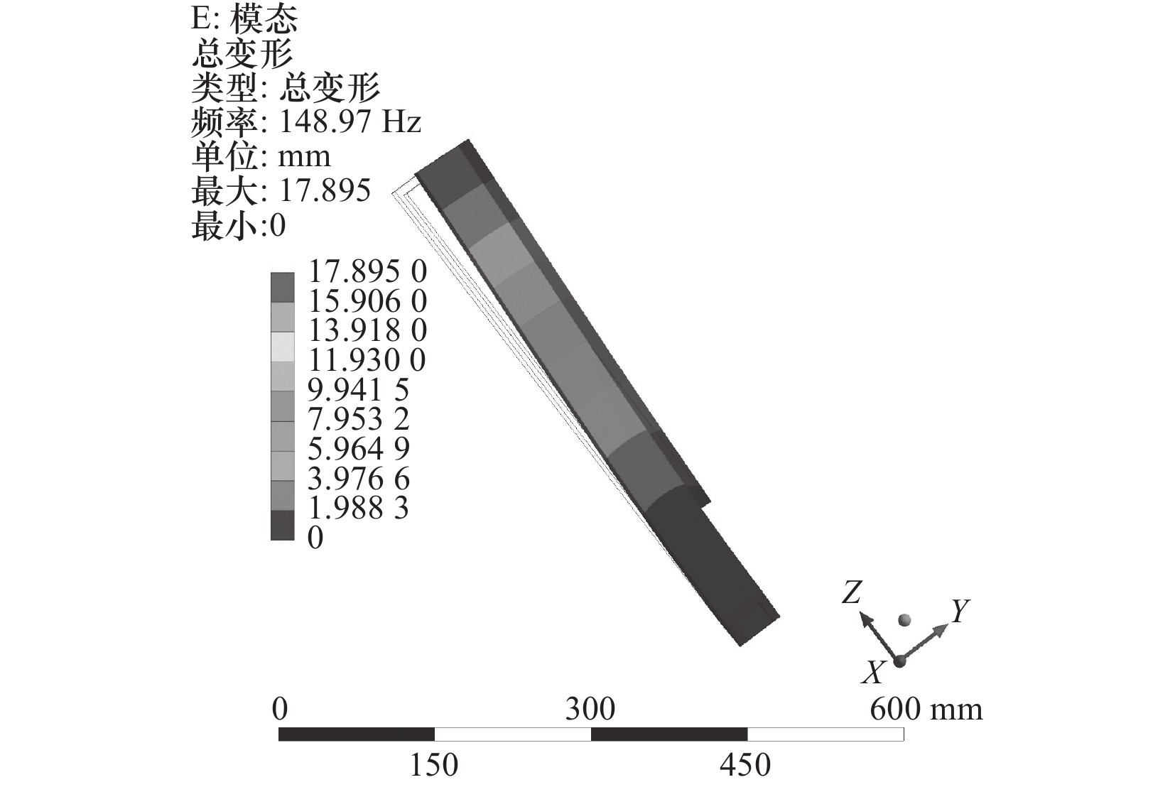
表 2 立柱模态分析结果
阶数 频率/Hz 振形特征 1 148.97 在y轴方向上前后摆动 2 243.34 在x轴方向上前后摆动 3 782.5 在y轴方向上扭动 4 827.48 绕z轴方向上扭动 5 1457.6 在x轴方向上扭动 6 1736.1 在y轴方向上扭动  下载: 导出CSV
表 3 设计参数数值
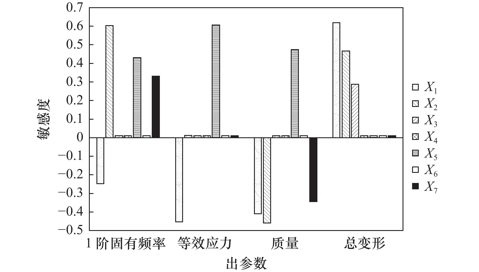
参数名称 变量名 初值/mm 范围/mm 前板厚 X1 8 4~12 背板厚 X2 8 4~12 左侧板厚 X3 8 4~12 右侧板厚 X4 8 4~12 切割矩形长 X5 100 50~150 连接板厚 X6 12 6~18 连接板长 X7 40 20~40
下载: 导出CSV
表 4 CCD试验设计结果
序号 设计变量 频率/
Hz应力/
MPa变形/
µm质量/
kgX1 X2 X3 X5 X7 1 8 8 8 100 30 176.30 8.77 120.35 10.00 2 4 8 8 100 30 173.77 11.76 136.32 8.42 3 12 8 8 100 30 169.32 7.99 112.51 11.58 4 8 4 8 100 30 160.38 9.32 138.84 8.76 5 8 12 8 100 30 180.05 8.52 113.15 11.24 6 8 8 4 100 30 173.63 9.53 126.94 9.63 7 8 8 12 100 30 177.08 8.47 116.12 10.38 8 8 8 8 50 30 165.90 8.39 116.79 10.51 9 8 8 8 150 30 177.31 14.40 138.77 9.49 10 8 8 8 100 20 176.28 8.88 121.56 9.98 11 8 8 8 100 40 176.32 8.75 119.19 10.03 12 6.87 6.87 6.87 85.83 32.83 172.14 8.79 126.75 9.23 13 9.13 6.87 6.87 85.83 27.17 169.40 8.22 121.14 10.11 14 6.87 9.13 6.87 85.83 27.17 175.78 8.72 121.18 9.95 15 9.13 9.13 6.87 85.83 32.83 173.82 8.05 114.07 10.86 16 6.87 6.87 9.13 85.83 27.17 172.63 9.14 124.36 9.45 17 9.13 6.87 9.13 85.83 32.83 170.04 8.08 118.13 10.35 18 6.87 9.13 9.13 85.83 32.83 176.37 8.95 117.64 10.18 19 9.13 9.13 9.13 85.83 27.17 174.46 7.87 112.31 11.05 20 6.87 6.87 6.87 114.17 27.17 175.77 10.07 132.35 8.95 21 9.13 6.87 6.87 114.17 32.83 172.81 9.42 124.17 9.87 22 6.87 9.13 6.87 114.17 32.83 180.27 9.89 125.08 9.65 23 9.13 9.13 6.87 114.17 27.17 177.94 9.31 118.60 10.54 24 6.87 6.87 9.13 114.17 32.83 176.72 9.86 127.84 9.19 25 9.13 6.87 9.13 114.17 27.17 173.76 9.14 121.88 10.06 26 6.87 9.13 9.13 114.17 27.17 181.23 9.80 122.57 9.84 27 9.13 9.13 9.13 114.17 32.83 178.94 8.97 115.76 10.75
下载: 导出CSV
表 5 优化候选点
候选点1 候选点2 候选点3 X1 8.12 8.12 8.19 X2 8.05 8.05 7.91 X3 11.05 10.92 11.35 X5 75.63 72.12 69.94 X7 30.35 29.98 23.12 频率/Hz 172.86 172.06 171.12 应力/MPa 8.10 8.12 8.18 变形/µm 113.51 113.48 113.5 质量/kg 10.62 10.64 10.67
下载: 导出CSV
表 6 设计参数数值
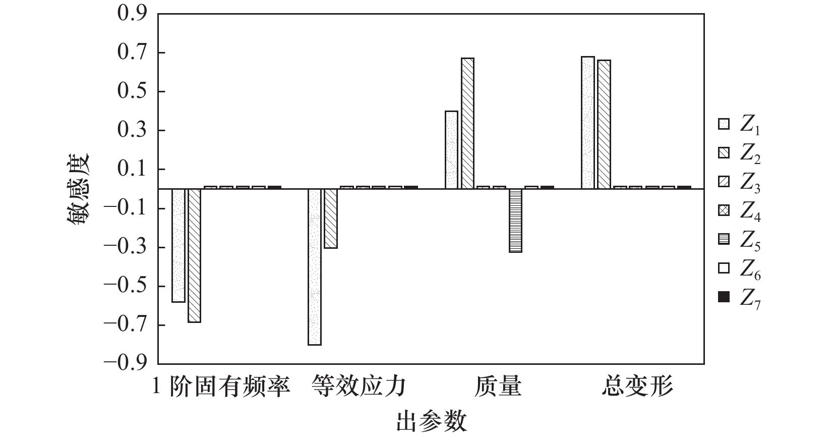
参数名称 变量名 初值/mm 范围/mm 前板厚 Z1 8 4~12 背板厚 Z2 8 4~12 左侧板厚 Z3 8 4~12 右侧板厚 Z4 8 4~12 顶板厚 Z5 8 4~12 连接板厚 Z6 12 6~18 连接板长 Z7 40 20~40
下载: 导出CSV
表 7 CCD试验设计结果
序号 设计变量 频率/
Hz应力/
MPa变形/
µm质量/
kgZ1 Z2 Z5 1 8 8 8 148.83 7.55 114.29 11.23 2 4 8 8 138.29 8.21 132.96 9.73 3 12 8 8 149.13 7.33 107.31 12.74 4 8 4 8 141.70 9.41 127.17 9.73 5 8 12 8 147.04 7.05 108.08 12.74 6 8 8 4 150.89 7.49 114.25 11.14 7 8 8 12 146.93 7.48 114.26 11.32 8 4.75 4.75 4.75 141.52 8.92 137.47 8.70 9 11.25 4.75 4.75 145.21 8.07 118.02 11.16 10 4.75 11.25 4.75 141.01 7.64 122.24 11.16 11 11.25 11.25 4.75 150.39 6.91 102.81 13.62 12 4.75 4.75 11.25 137.09 9.15 137.53 8.87 13 11.25 4.75 11.25 142.12 8.79 118.06 11.30 14 4.75 11.25 11.25 137.94 7.90 122.26 11.30 15 11.25 11.25 11.25 148.23 6.96 102.74 13.73
下载: 导出CSV
表 8 优化候选点
变量名 候选点1 候选点2 候选点3 Z1 7.41 7.41 7.42 Z2 8.65 8.63 8.68 Z5 4.1 4.24 4.80 频率/Hz 151.06 150.96 150.63 应力/MPa 7.43 7.44 7.47 变形/µm 113.87 113.92 113.82 质量/kg 11.17 11.16 11.2
下载: 导出CSV
表 9 立柱结构优化分析结果
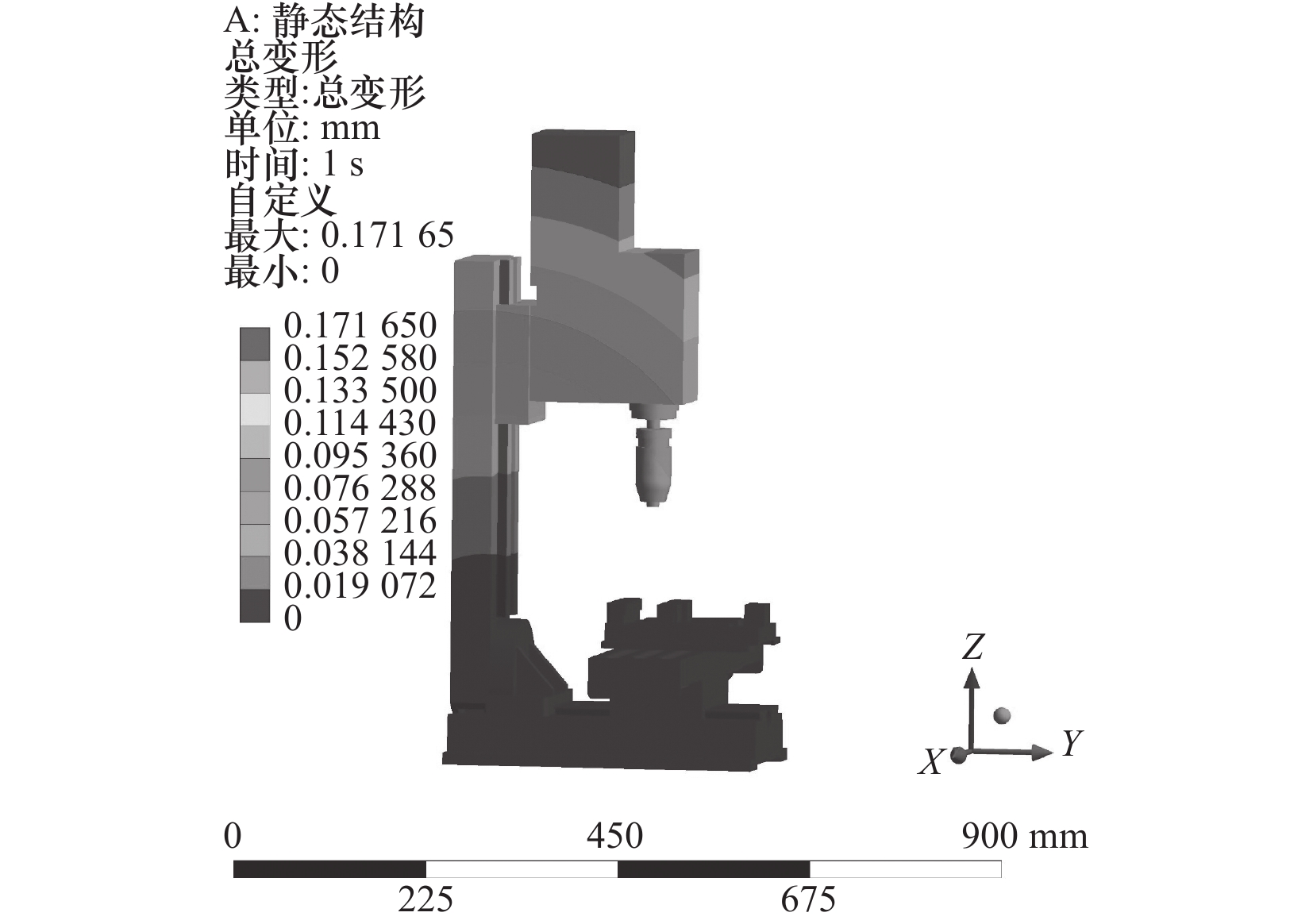
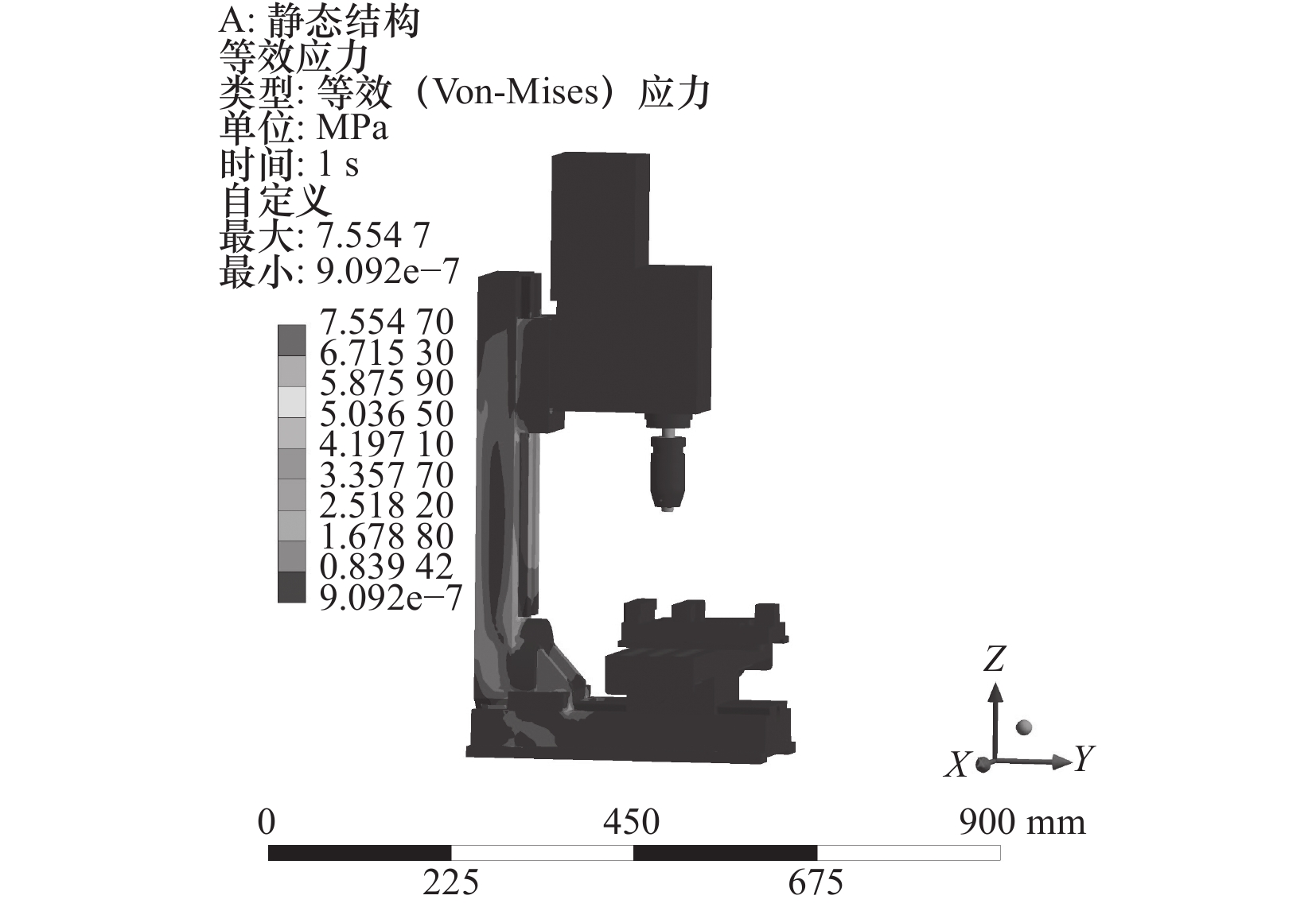
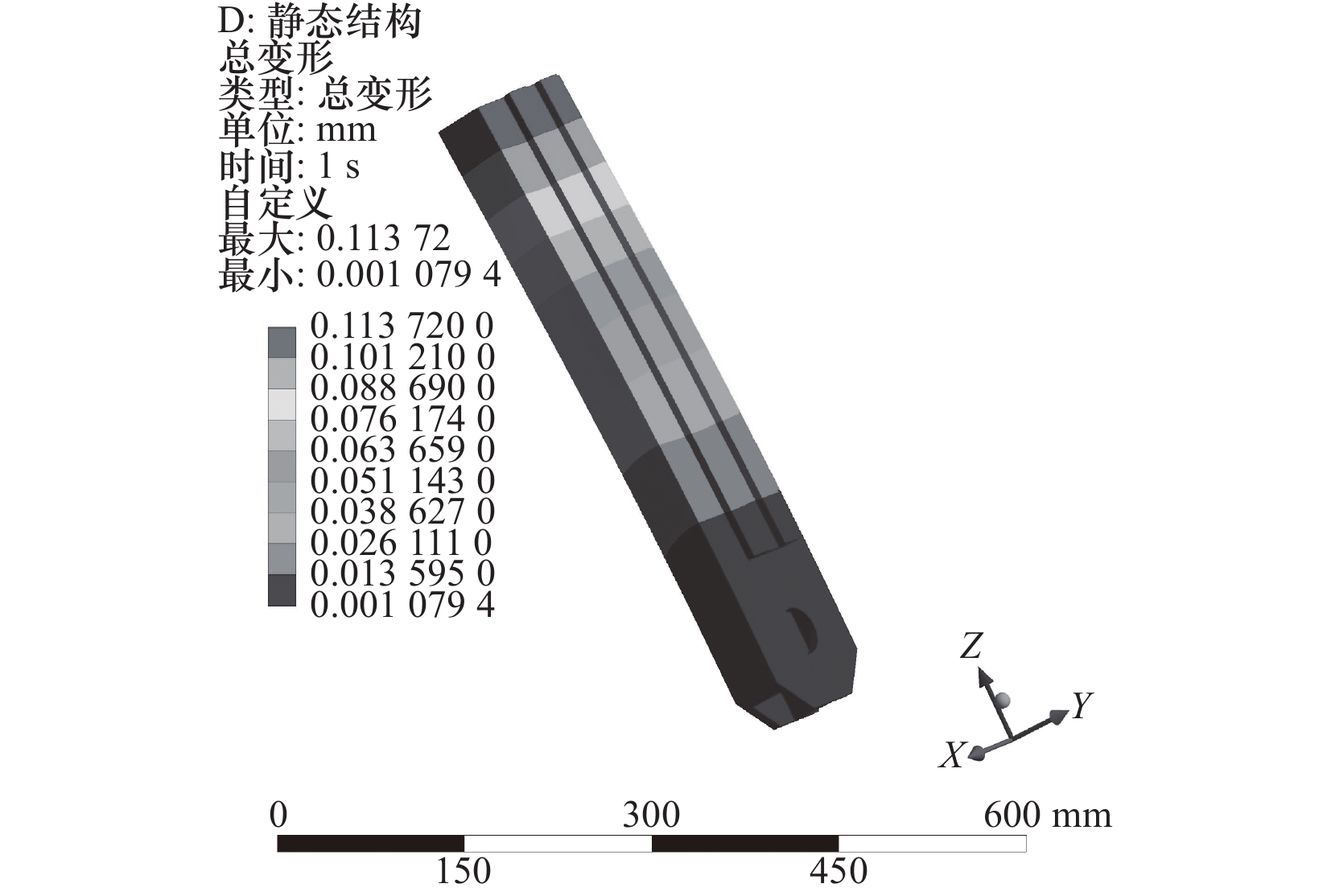
状态 频率/Hz 应力/MPa 变形/µm 质量/kg 原始 148.97 7.56 113.72 11.18 拓扑 177.39 9.02 120.32 9.97 差值/(%) +19.1 +19.3 +5.8 −10.8 尺寸 150.96 7.44 113.92 11.16 差值/(%) +1.3 −1.6 +0.2 −0.2 拓扑+尺寸 172.86 8.10 113.51 10.62 差值/(%) +16 +7.1 −0.2 −5.3
下载: 导出CSV
-
[1] 郑彬. 数控钻床立柱有限元分析及轻量化设计[J]. 机械设计,2019,36(S2):99-103. [2] 仇君,朱晓慧,黄伟,等. 立式钻床立柱结构动静态分析与结构改进[J]. 机床与液压,2012,40(7):152-155. [3] 董斌,鄢威,张华. 基于ANSYS的数控铣床立柱性能分析及结构优化[J]. 组合机床与自动化加工技术,2017(6):22-25. [4] 蒲凡,胡光忠,邹亮,等. 立式加工中心立柱动静态特性分析与拓扑优化[J]. 现代制造工程,2017(1):70-75,81. [5] 李源,黄华,郭润兰. 基于响应面法的加工中心立柱结构多级多目标参数优化设计[J]. 机械设计,2019,36(11):44-49. [6] 刘梅清,白耀华,李秋玮,等. 基于逆向工程的双吸离心泵三维建模及数值模拟[J]. 中国农村水利水电,2011(1):152-155. [7] 闫磊,冯兰芳,惠延波,等. 基于逆向工程的支架零件优化设计及快速成型[J]. 制造业自动化,2019,41(6):30-33. [8] 周小东,成思源,杨雪荣,等. 基于逆向工程的参数化优化设计[J]. 组合机床与自动化加工技术,2016(3):37-40. [9] 仇灿华,成思源,张湘伟,等. 基于反求工程技术的零件有限元分析[J]. 机械设计与制造,2009(9):35-36. -

 下载:
下载:


 点击查看大图
图(20) / 表(9)
计量
- 文章访问数: 53
- HTML全文浏览量: 21
- PDF下载量: 19
- 被引次数: 0