A spatial error modeling method under the influence of multiple error factors
-
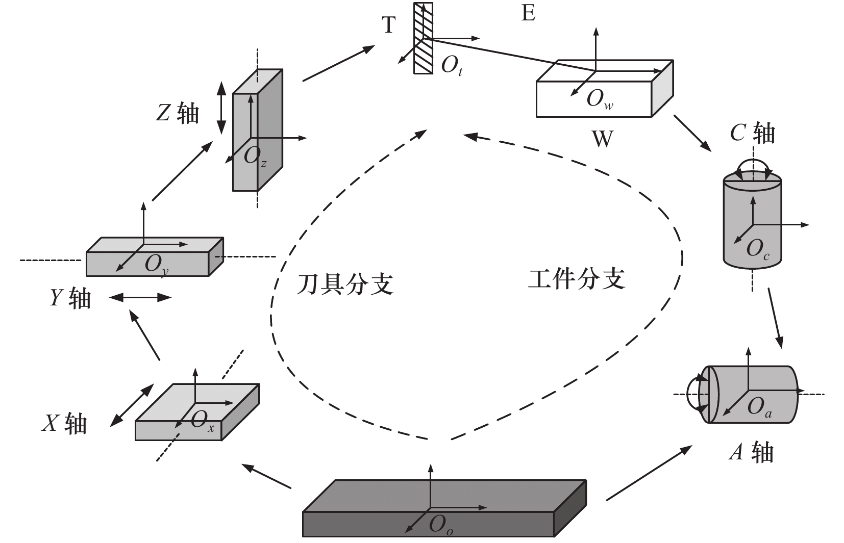
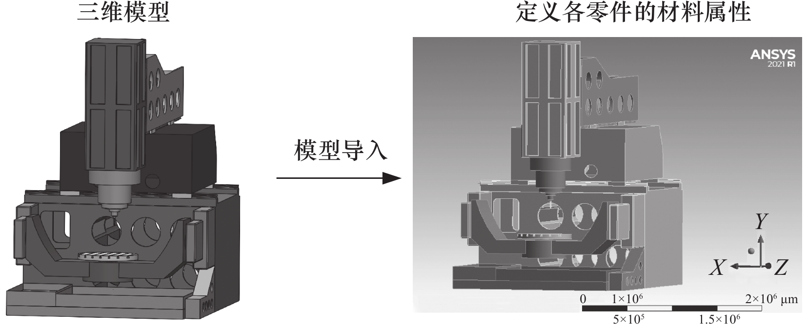
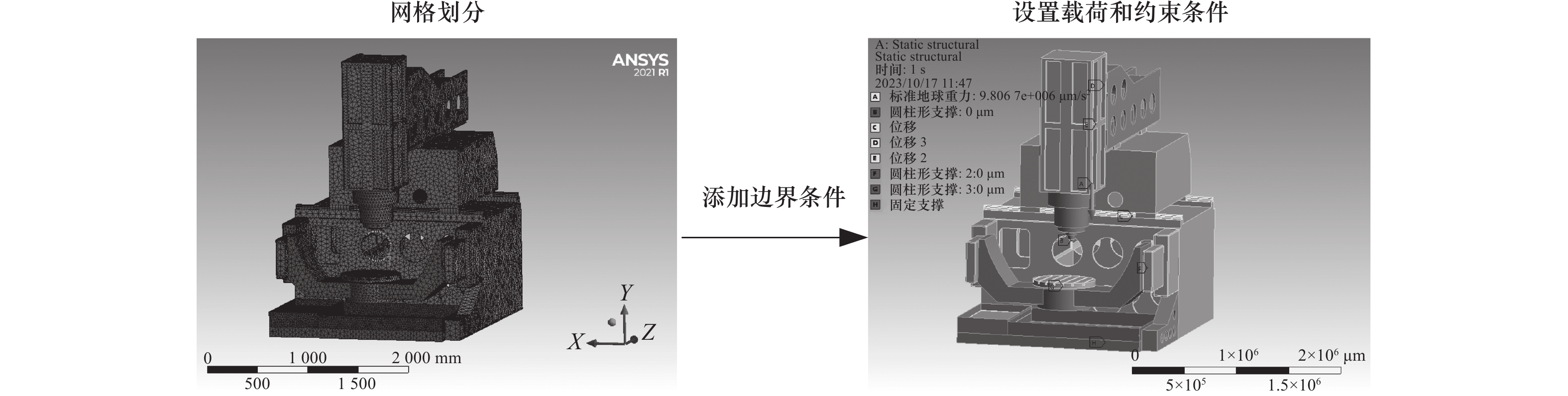
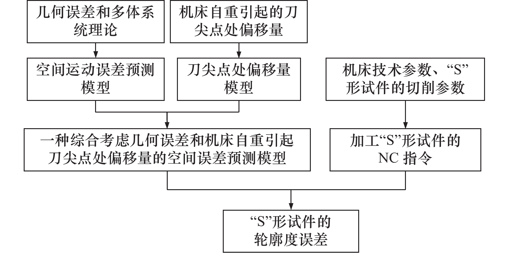
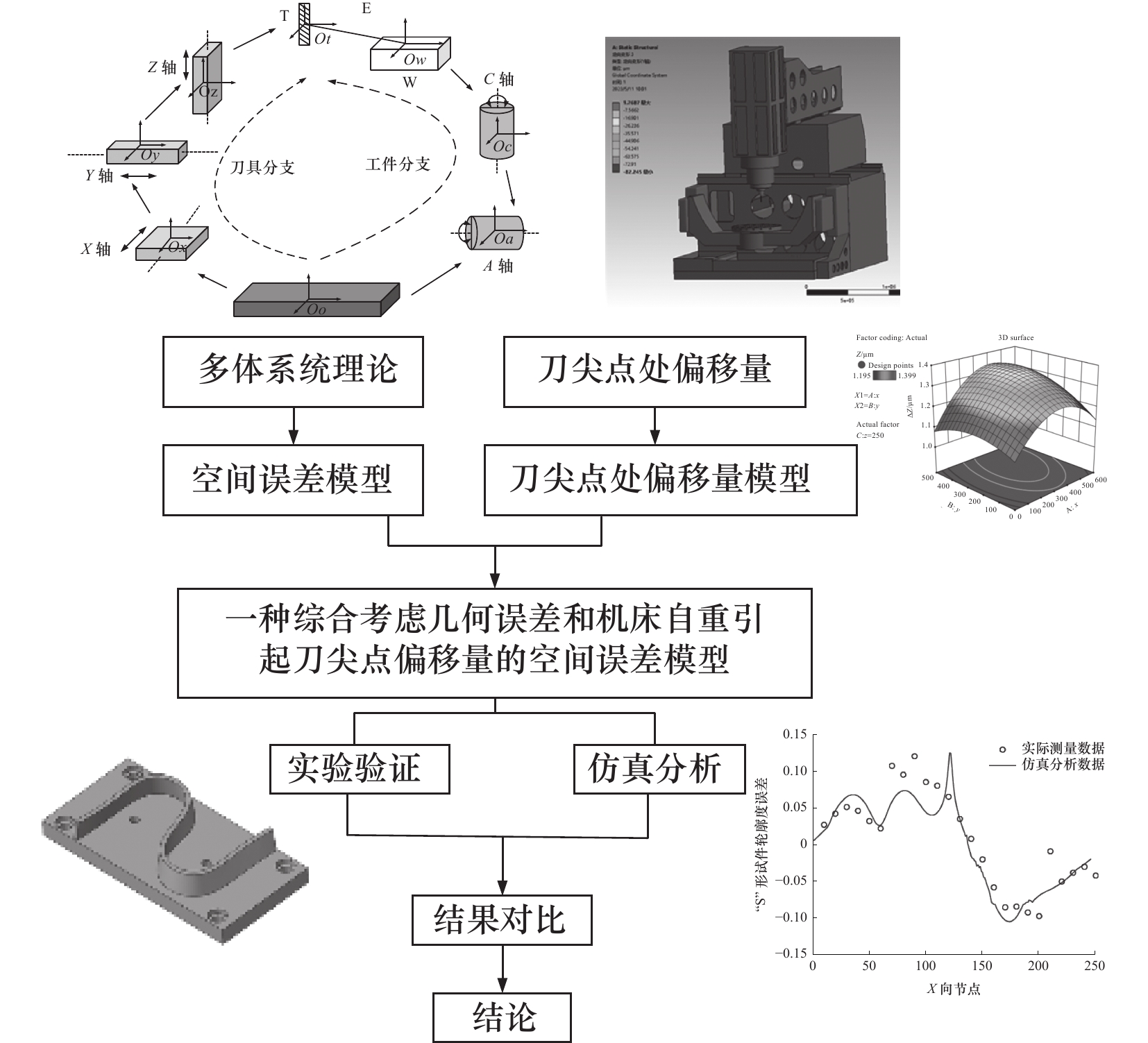
摘要: 目前,关于机床空间误差建模的研究较少考虑由于机床自重引起刀尖点处的偏移量,导致空间误差模型的预测精度与实际结果存在偏差。为了解决上述问题,文章提出一种综合考虑几何误差和机床自重引起刀尖点处偏移量的空间误差建模方法。首先,基于多体系统理论和齐次坐标变换原理建立机床空间误差模型,其次利用正交实验法选出25组加工点,通过仿真分析得到样本点处机床自重引起的刀尖点处偏移量,并通过拟合建立刀尖点偏移量模型,揭示了刀尖点偏移量随加工位置的变化规律,从而建立了一种综合考虑几何误差和机床自重引起刀尖点处偏移量的空间误差模型,最终以“S”形试件为研究对象,进行仿真分析和实验验证,通过对比预测结果和实验结果发现获得的“S”形试件的轮廓误差变化趋势基本相同,残差值较小且低于测量结果的10%,验证了该方法的正确性。该方法的核心思想适用于各类多轴机床。Abstract: At present, the deviation caused by the weight of the machine tool at the tool tip is rarely considered in the spatial error model of machine tools, which leads to a deviance between the prediction accuracy of the spatial error model and the actual results. To address the issues, a synthesis modeling method for geometric errors and the deviation at the tool tip caused by the machine tool’s self-weight is introduced in this paper. In the initial phase, the spatial error model of machine tools is established based on multi-body system theory and the homogeneous coordinate transformation matrix. Subsequently 25 machining points are selected for analysis, which employ orthogonal design. The simulation analysis is conducted to ascertain the deviation caused by the weight of the machine tool tip for the 25 machining points. A tooltip deviation model is formulated using polynomial fitting, elucidating the variation of tooltip deviation in the machine operation. Consequently, a synthesis modeling method for geometric errors and the deviation at the tool tip caused by the machine tool’s self-weight is devised. In the final stage, the S-shaped test piece is selected as the research object, Simulation analysis and experimental verification show that the contour error trend of the obtained S-shaped specimen is basically the same, and the residual value is small and less than 10% of the measurement result, which verifies the correctness of the method proposed in this article. The core idea of this approach applies to all types of multi-axis machines.
-
表 1 加工位置坐标点
mm 加工点 X Y Z 加工点 X Y Z 1 120 100 100 14 360 400 500 2 120 200 300 15 360 500 200 3 120 300 500 16 480 100 300 4 120 400 200 17 480 200 500 5 120 500 400 18 480 300 200 6 240 100 500 19 480 400 400 7 240 200 200 20 480 500 100 8 240 300 400 21 600 100 200 9 240 400 100 22 600 200 400 10 240 500 300 23 600 300 100 11 360 100 400 24 600 400 300 12 360 200 100 25 600 500 500 13 360 300 300  下载: 导出CSV
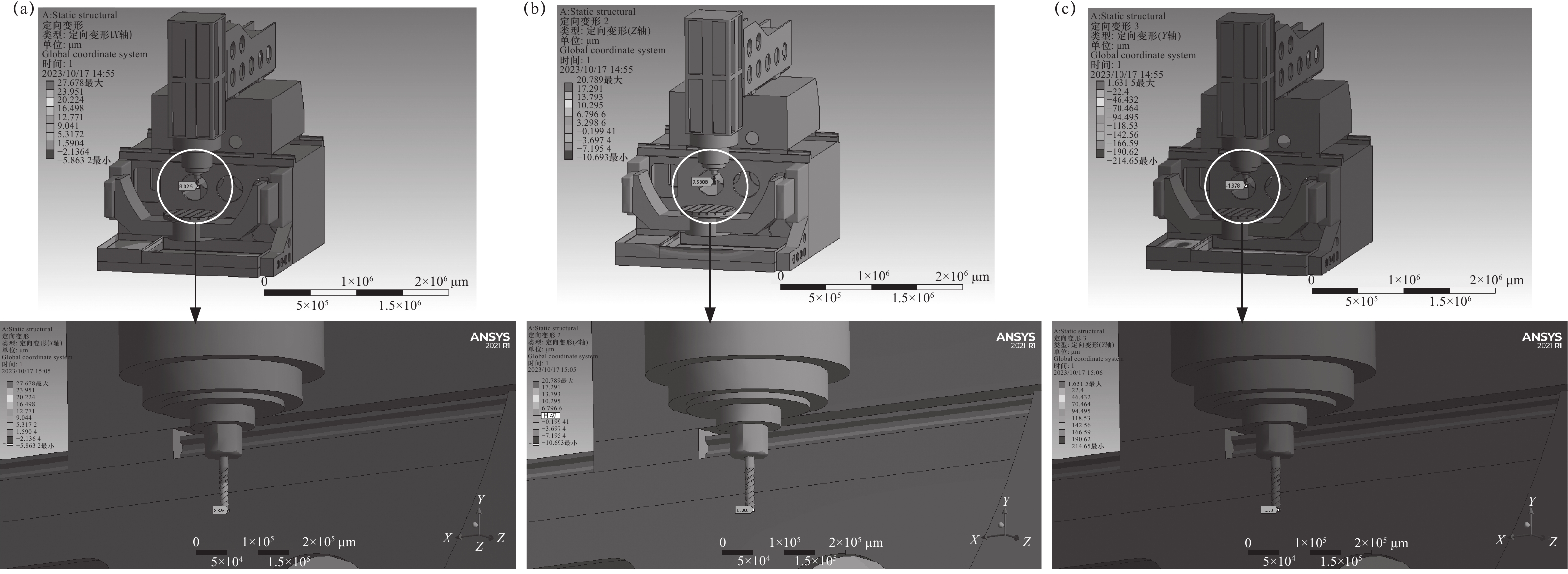
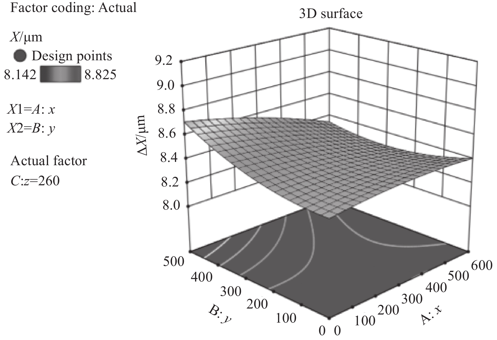
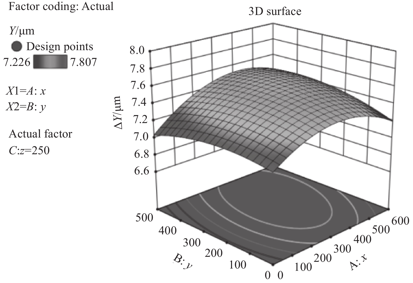
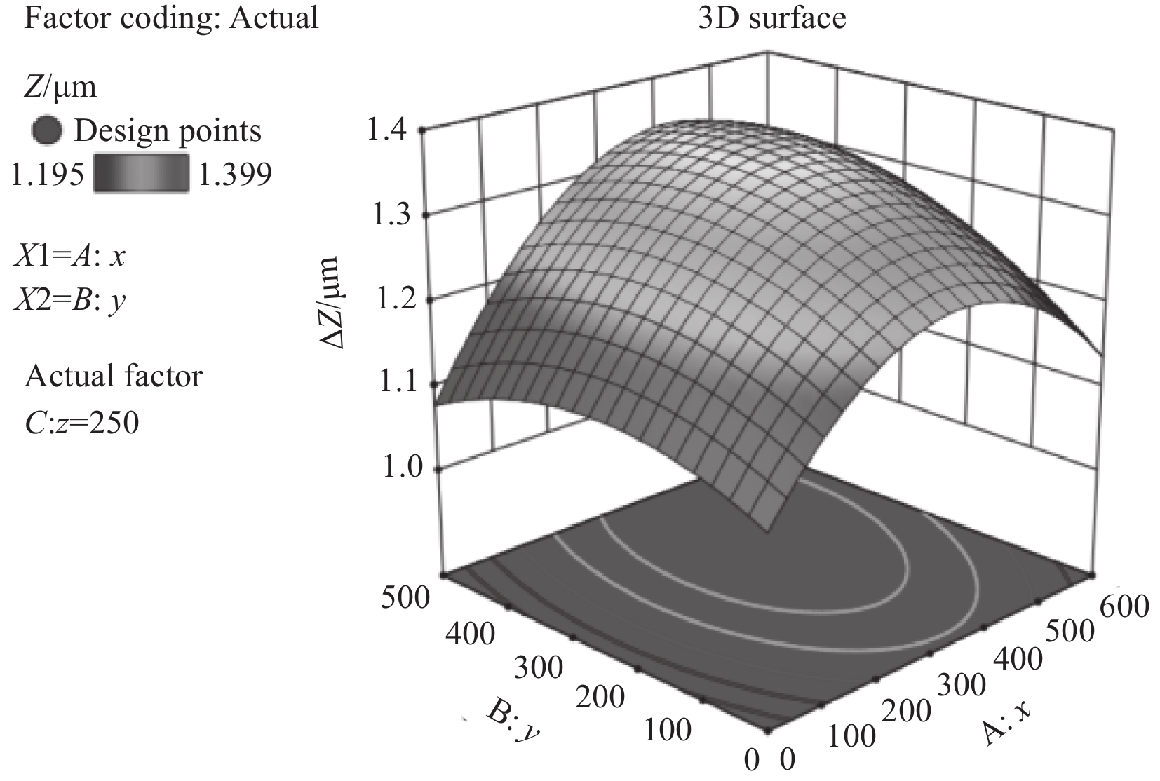
表 2 刀尖点处偏移量
μm 加工点 X Y Z 加工点 X Y Z 1 8.369 7.338 1.208 14 8.375 7.393 1.387 2 8.671 7.301 1.217 15 8.326 7.531 1.378 3 8.142 7.342 1.293 16 8.379 7.352 1.298 4 8.296 7.361 1.289 17 8.76 7.353 1.214 5 8.363 7.306 1.289 18 8.789 7.547 1.289 6 8.371 7.479 1.306 19 8.483 7.497 1.371 7 8.32 7.584 1.286 20 8.736 7.441 1.391 8 8.197 7.446 1.344 21 8.324 7.423 1.195 9 8.716 7.413 1.295 22 8.682 7.226 1.207 10 8.718 7.362 1.206 23 8.323 7.528 1.326 11 8.753 7.351 1.339 24 8.355 7.314 1.292 12 8.353 7.348 1.352 25 8.825 7.246 1.199 13 8.572 7.807 1.399
下载: 导出CSV
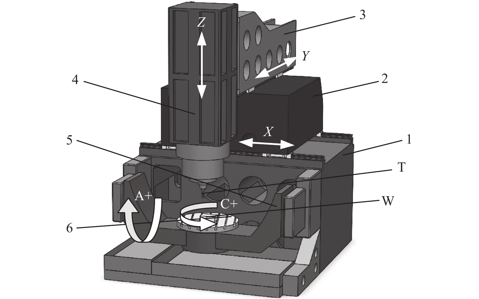
表 3 LINEARMILL-600HD五轴数控机床主要技术参数
机床配置 参数值 工作台尺寸(宽×长)/(mm×mm) 600×600 直线轴的行程(X,Y,Z)/mm 6 000,5 000,5 000 摆动轴行程(Rc,Ra)/mm ±360°,±120° 标准主轴转速/(r/min) 15 000 直线轴快速运动速度/(r/min) ≥60 直线轴切削进给速度/(m/min) ≥20 直线轴直线加速度/(m/s2) ≥10
下载: 导出CSV
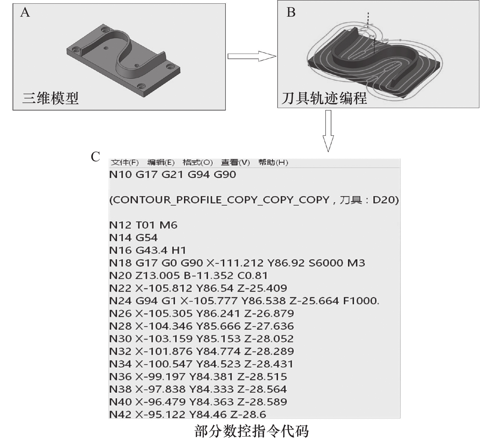
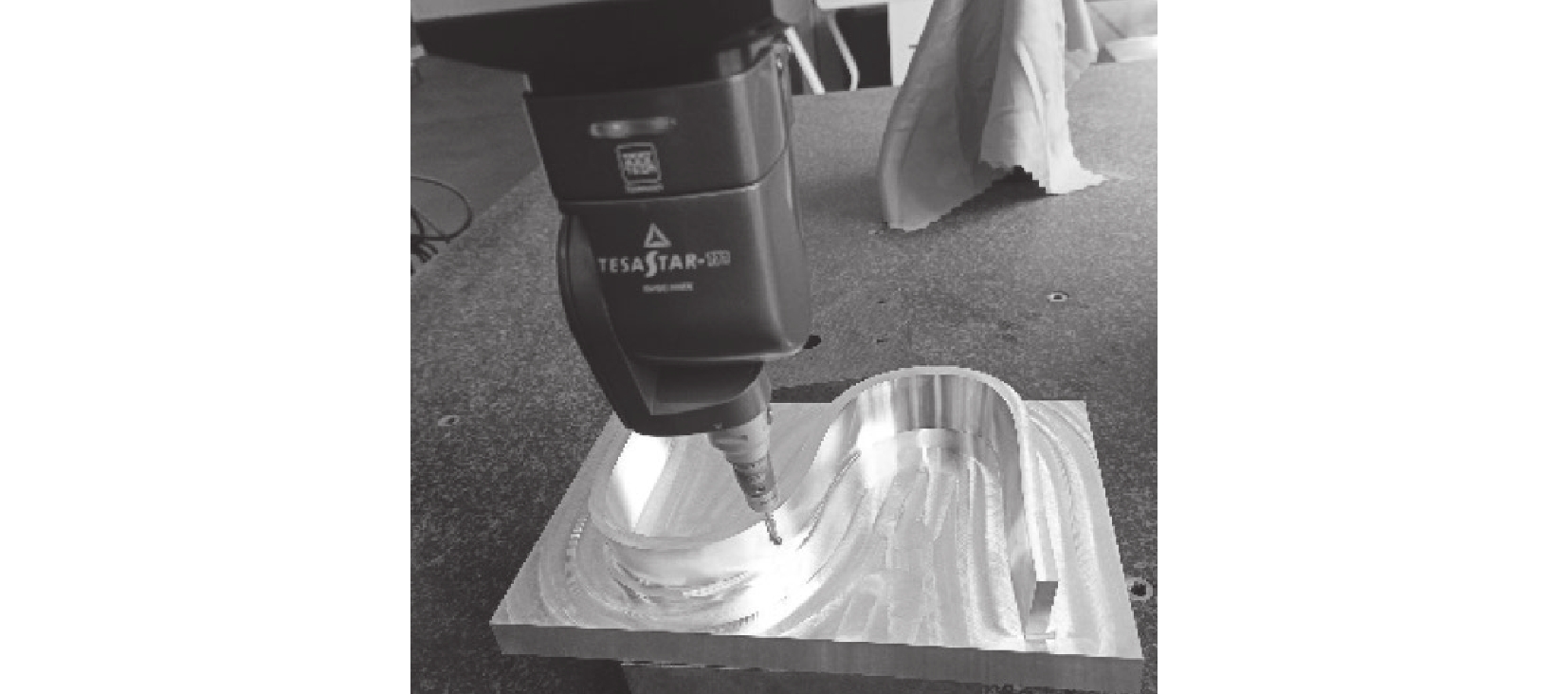
表 4 “S”形试件的尺寸和参数
参数类型 参数值 整体未加工尺寸/(mm×mm) 400×200 “S”形试件外形尺寸/(mm×mm) 250×180 方形基座高/mm 30 “S”形缘条高/mm 40 材料类型 2A12高强度铝合金
下载: 导出CSV
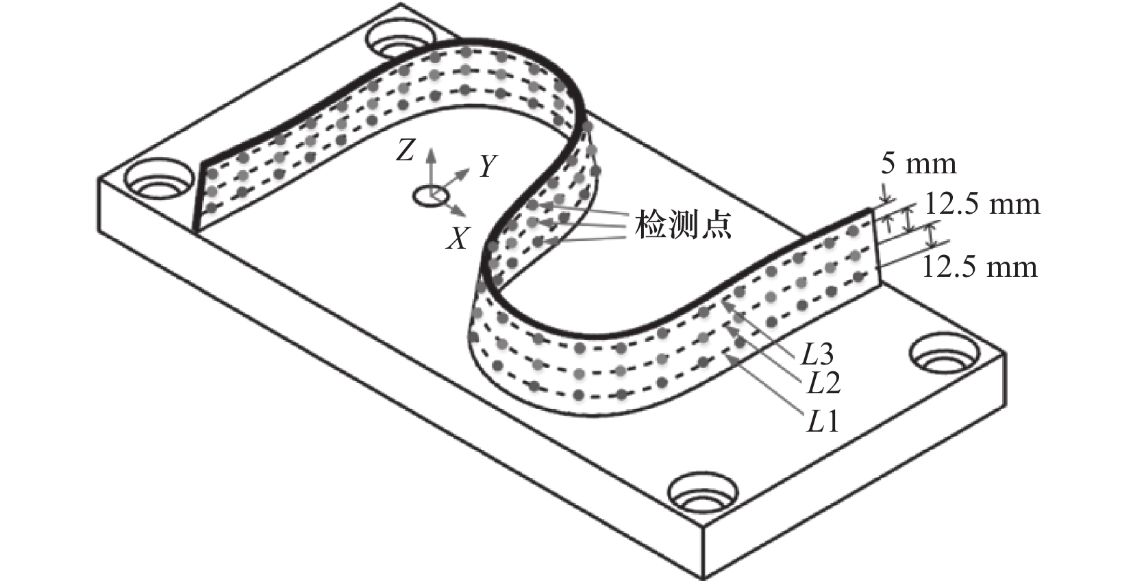
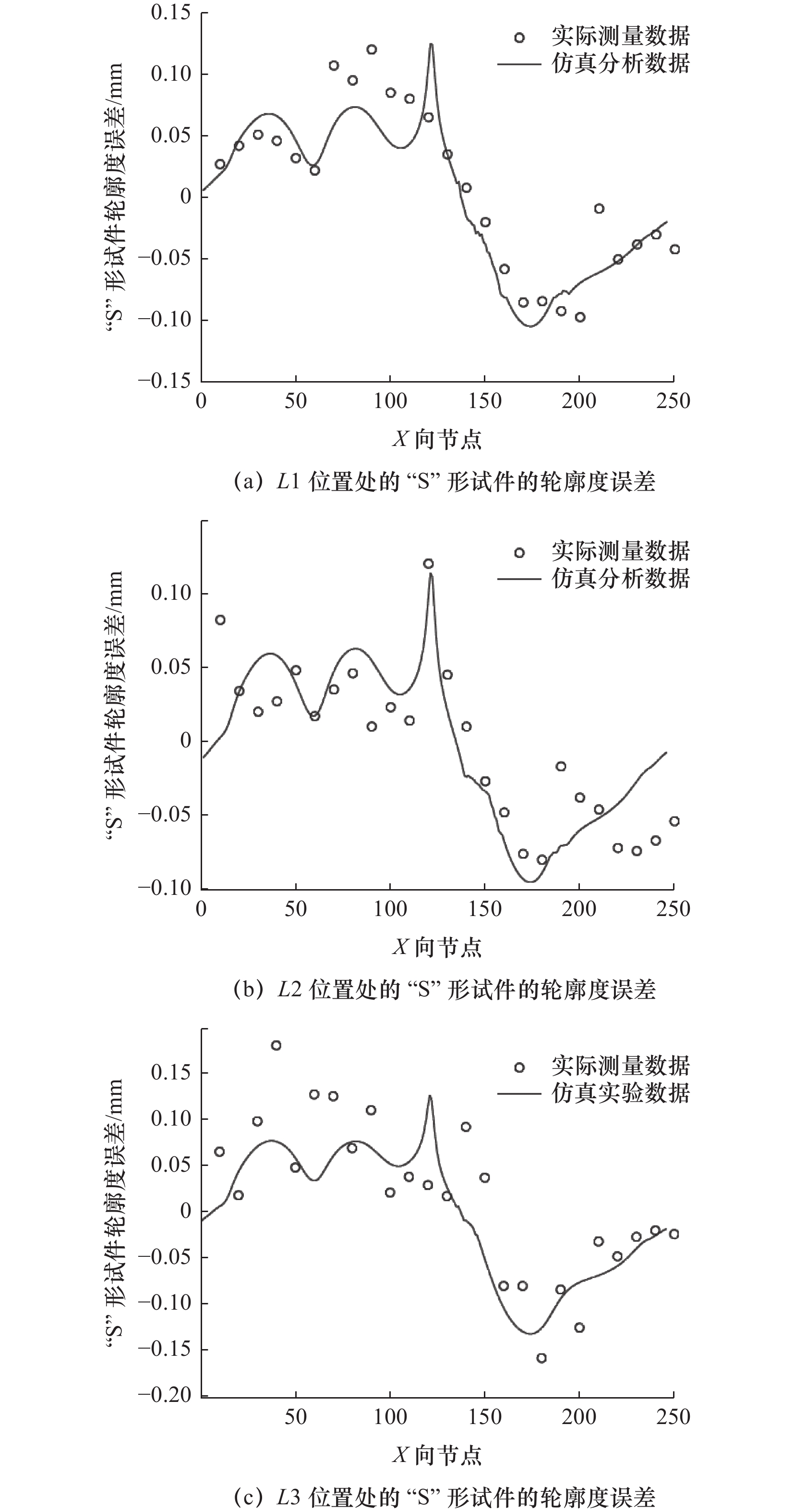
表 5 “S”形试件平均轮廓度误差对比
检测线 平均轮廓度误差/mm 残差/mm 仿真分析 实际测量 L1 0.058 4 0.055 3 0.003 1 L2 0.048 3 0.045 5 0.002 8 L3 0.059 4 0.055 2 0.004 2
下载: 导出CSV
-
[1] Chen Y T,Lee T Y,Liu C S. Synchronous measurement and verification of position-independent geometric errors and position-dependent geometric errors in C-axis on mill-turn machine tools[J]. Advanced Manufacturing Technology,2022,121(7-8):5035-5048. doi: 10.1007/s00170-022-09648-5 [2] Viprey F,Nouira H,Lavernhe S,et al. Modelling and characterisation of geometric errors on 5-axis machine-tool[J]. Mechanics and Industry,2019,20(6):1-8. [3] Fan J W,Qian Y. Research on geometric error modeling and compensation method of CNC precision cylindrical grinding machine based on differential motion theory and Jacobian matrix[J]. Advanced Manufacturing Technology,2022,120(3-4):1805-1819. doi: 10.1007/s00170-022-08882-1 [4] 柏衡,沈建新. 基于多体系统理论的数控机床综合误差建模技术[J]. 航空制造技术,2017(Z1):117-121,124. [5] 项四通,杨建国,Altintas Y,等. 五轴数控机床空间误差测量、建模与补偿技术研究[J]. 机械工程学报,2018,54(4):108. [6] 郭前建,赵国勇,程祥,等. 双转台五轴机床空间误差补偿技术研究[J]. 机械工程学报,2016,52(13):189-194. [7] 范晋伟,陶浩浩,王鸿亮,等. 基于多体系统理论的机床建模与几何误差分析[J]. 制造业自动化,2016,38(11):52-56,61. doi: 10.3969/j.issn.1009-0134.2016.11.012 [8] 郭世杰,武建新,乔冠,等. 数控机床几何误差正弦低次多项式参数化建模与应用研究[J]. 仪器仪表学报,2020,41(10):136-146. [9] 章子玲,胡雄,亓寅,等. 基于向量投影响应面的数控机床几何误差分配方法[J]. 吉林大学学报:工学版,2022,52(2):384-391. [10] 王艳红,喻伟男,李冬,等. 五轴数控机床非线性误差建模及补偿方法[J]. 组合机床与自动化加工技术,2022(2):25-28. [11] 张根保,范秀君. 机床关键几何误差辨识方法研究[J]. 中国机械工程,2014,25(7):853-856. doi: 10.3969/j.issn.1004-132X.2014.07.001 [12] 王洪乐,周青华,熊青春. 基于多体系统理论的数控机床加工精度几何误差预测模型[J]. 制造技术与机床,2018(5):78-83. [13] 边志远,丁杰雄,赵旭东,等. 基于“S”件的五轴数控机床加工性能综合评价方法研究[J]. 组合机床与自动化加工技术,2015(2):86-89. [14] 陶浩浩,范晋伟,王培桐. 一种减小“S”形试件理论切削误差的方法[J]. 机械工程学报,2020,56(17):209-215. [15] 杨婧,冯其波. 数控机床空间几何误差测量研究进展[J]. 仪器仪表学报,2017,38(8):1901-1911. doi: 10.3969/j.issn.0254-3087.2017.08.008 [16] 代康,张松,舒雨,等. 数控机床平动轴几何误差辨识方法改进[J]. 计算机集成制造系统,2021,27(5):1319-1327. [17] Song Z Y,Cui Y W. S-shape detection test piece and a detection method for detection the precision of the numerical control milling machine:US8061052B2 [P]. 2010-01-07. -

 下载:
下载:

 点击查看大图
图(15) / 表(5)
计量
- 文章访问数: 29
- HTML全文浏览量: 19
- PDF下载量: 2
- 被引次数: 0